The ICS 2X Repeater Boards as used in the USA currently used with the ORP version of SVXLink. For all information go to https://ics-ctrl.com/ – this article updated 03-09-2026 (US Date) as the 4X board installation continues. There are three chapters. ** Note – Reversal of the MCP chips in Chapter 2
Please note that I have aliased all the GPIO Lines and Sound Card References to fit the Port numbers. So port 1 will have Tx1 Rx1 soundcard rx1 and so on. This arrangement will appear in the upcoming images ready configured for the ICS Cards, particularly the 4X. There is likely to be an update to Chapter 2 Imminently. Just awaiting the result of some tests.
- Chapter 1 – Some generalities and the 2x board
- Chapter 2 – the 4x board
- Chapter 3 – The requirements of SvxLink to run more than one logic of one type at a time
For the 4 channel boards, read the second chapter after reading the first.
Chapter 1.
As it stands at the moment, the OpenRepeaterSoftware for these boards cannot be used in the same way as the current and latest versions 24 and 25 of SVXLink, as the ORP software was developed from Version 17.
It has no ReflectorLogic as this was a later development. So if you would like to network your repeater through an SvxReflector with Analog Talkgroups, then you will need to start from scratch. Read On.
I have recently successfully installed the new version of Svxlink Version 25, remotely on a GMRS Repeater in Wyoming for the keeper. Naturally this repeater has no operational networking as it is forbidden for this band.
However for those of you familiar with this board, know that it is very well engineered but building the newer svxlink software is a little bit of a challenge because of the onboard sound card(s) and the extended GPIO bus ports.
As Raspberry OS Trixie has been released only recently, I am personally reluctant to use it due to the uncertainty of some of the additional packages having no release under Debian 13 or the versions have to be changed in various scripts. So we remain using Bookworm (Raspberry Pi OS and Debian12)
So for the purposes of stability follow these instructions first to install svxlink. Although the instructions suggest to run the installation command do not do so until after you have followed the below list first.
Firstly go to https://ukwide.svxlink.net/downloads and download the image, and the instructions. Do not unzip the image, and let the Raspberry Pi Imager perform the install. NB this will change with the upcoming image specifically for ICS Cards.
Use RaspberryPi Imager to install the image, but select in the choose device box select “No filtering”. Then select from your downloads the svxlink.img.gz. In the final button choose your sdcard.
On next do not – I repeat do not select your saved profile – install it without, you can change your password later. Write and verify the card.
Now transfer it to the raspberry pi and power it up, and when established, log into the terminal ssh [email protected] – yes – you should not need to know the IP address at this stage, but if you have angry IP scanner then go ahead. To log in, the user name is pi, and the password is raspberry. Do not under any circumstances use root, it defies protocol.
After examining the manuals for the ICS repeaters, there will be noticeable differences to point out in addition to the normal install. Watch for these as we proceed.
- Our first task is to sudo raspi-config and enable the i2c port in the peripherals menu. You do not need to reboot at this stage.
- Our second task is to enable the mcp23017 chipset in the ICS card so that it can be used with the Raspberry Pi. We create a file in terminal, preferable one of the locations readily accessible such as the /etc/ folder.
sudo nano /etc/ics-repeater.dts and introduce the following content into it, then saving the file and exiting nano.
/dts-v1/;
/plugin/;

/ {
compatible = "brcm,bcm2835";
fragment@0 {
    target = <&i2c1>;
    __overlay__ {
        #address-cells = <1>;
        #size-cells = <0>;
        mcp23017@20 {
            compatible = "microchip,mcp23017";
            reg = <0x20>;
            gpio-controller;
            #gpio-cells = <2>;
            gpio-line-names =
                "GPIO496", "GPIO497", "GPIO498", "GPIO499",
                "GPIO500", "GPIO501", "GPIO502", "GPIO503",
                "GPIO504", "GPIO505", "TX1", "TX2",
                "GPIO508", "GPIO509", "GPIO510", "GPIO511";
        };
    };
  };
};
now compile this file in the command line:
sudo dtc -@ -I dts -O dtb -o /boot/firmware/overlays/ics-repeater.dtbo /etc/ics-repeater.dtsNow we have to enable all the other aspects of the software.
sudo nano /boot/firmware/config.txtOlder versions had this file at /boot/config.txt, but bookworm doesn’t – just be aware.
Scroll to the bottom of the existing contents of this file and add the following lines.
# ICS Required Drivers/Overlays
#
dtoverlay=fe-pi-audio
dtoverlay=12s-mmap
# Enable mcp3208 adc overlay
dtoverlay=mcp3208:spi0-0-present,spi0-0-speed=1000000
# Enable the new gpiod numbers
dtoverlay=ics-repeater
Now would be as good a time as any to reboot the Raspberry Pi and logging back into the terminal.
To check the connection to the ICS card you can do two things.
- aplay -L will show the addition of the sound card.
- sudo gpioinfo will display the content of the GPIO interface at gpiochip0 and gpiochip3 with the newly named gpio ports on the extended GPIO interface.
(Author’s note – Do not run this next block unless you have issue with the audio – I suspect everything will be fine without it. skip to the next item)
The next stage is to prepare the sound card. Type sudo nano /etc/asound.conf and paste the following settings.
ctl.!default {
type hw
card 0
}

pcm.dmixed {
type dmix
ipc_key 1024
ipc_key_add_uid 0
slave.pcm "hw:0,0"
}

pcm.dsnooped {
type dsnoop
ipc_key 1025
slave.pcm "hw:0,0"
}

pcm.duplex {
type asym
playback.pcm "dmixed"
capture.pcm "dsnooped"
}

pcm.shared_left {
type plug
slave.pcm "hw:0"
slave.channels 2
ttable.0.0 1
}

pcm.shared_right {
type plug
slave.pcm "hw:0"
slave.channels 2
ttable.1.1 1
}

pcm.left {
type asym
playback.pcm "shared_left"
capture.pcm "dsnooped"
}

pcm.right {
type asym
playback.pcm "shared_right"
capture.pcm "dsnooped"
}

pcm.hw_loopback {
type hw
card "Loopback"
device 1
subdevice 2
}

pcm.plug_loopback {
type plug
slave.pcm "hw_loopback"
ttable {
0.0 1
0.1 1
}
}

pcm.!default {
type plug
slave.pcm "duplex"
}
Save the file and exit nano.
sudo alsactl nrestore followed by aplay -L will show all the additional modules created by the around.conf file – ignore any errors that might appear, there is a slight bug in alsa.
Next set the following amixer settings or preferably use sudo alsamixer. At the completion of these commands sudo alsactl store will keep them in place after a reboot at any time. Make sure all the setting in Alsamixer are enabled. The image below is minimalist and there will be more columns present that pictured below. Look carefully to unmute any “capture” column but selecting the column and typing M. Unmuted should show ‘oo’ at that position.
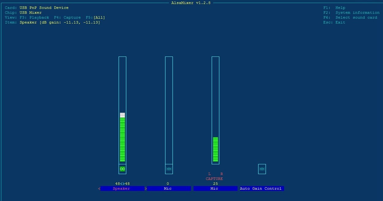
amixer set 'Headphone' 86%;
amixer set 'PCM' 75%;
amixer set 'Lineout' 58%;
amixer set 'Mic' 59%;
amixer set 'Capture Mux' LINE_IN;
Now we are ready for the svxlink software. In the terminal at the root directory – the one you log into, type
./svxlinkbuilder/install.sh
This starts the menu where you make your selections for the build. We are building a repeater of course, so you will be presented with a choice of ‘with or without’ svxreflector. If you choose ‘with’ it will install the UK reflector. However when you have another svxreflector to which to connect, the field will be editable, together with the port number (5300 by default) later. Callsigns and Authorisation Keys are also editable as required. If you want to test the UK reflector send me an email with your callsign, and I’ll send you an authorisation key.
Menus:
- Choice of Language. If you choose USA, all the options will install USA voice samples and airports.
- The next choice will be for the SA818 cards where the answer is NO.
- You next choice will be over the USB soundcard, you will choose number 3 – Unmodified, you will get your choice of GPIO port next. You may need to edit them anyway but hit that button. You will be able to choose PTT_GPIOD_LINE = 10 for the PTT, and 26 for the SQL/COS. Both will be Active High. The difference here is that in [Tx1] and [Tx2] PTT_GPIOD_CHIP = gpiochip3 (maybe gpiochip2) and SQL_GPIOD_CHIP = gpiochip0 – Recap – Tx1 PTT_GPIOD_LINE = 10 and tx2 PTT_GPIOD_LINE = 11. There is no need to use the names we gave!
- Choose your node type – simplex or repeater with or without reflector
- Enter the node callsign – then wait for your chosen language samples to be loaded, it may take a while.
- Next Enter the user name for the upcoming dashboard, and a password for editing it later.
- Next Enter the Authorisation Key provided by your svxreflector manager. Under normal circumstances Version 25 would use X509 certification with a protocol 3 reflector, however this build is set for simplicity and a protocol 2 reflector. If you need to change, you can change later.
- Your PTT is next Normally Active Low here. Choose 10 from the menu in the next box as a Custom entry, remembering that we need to check PTT_GPIOD_CHIP when we get there.
- The SQL/COS will be normally be Active High then select Custom on the next menu then type 26 in the next menu
- Choose your time format 12 or 24 hours.
- The next value you type MUST be a Minus value so type -10 (minus 10 or minus 12) but it must be minus. If you don’t it will prevent the svxlink from running, but you can edit it in the [RepeaterLogic] in the svxlink.conf later….. but it must be -10 or less (-11,-12,-13).
- Next type in the pitch of any CW if you choose to use it. Put 650 in here. That’s the standard tone in hertz on HF.
- In the next box put something in the range of 95-120 here – it will be the speed in characters per minute.
- Svxlink as standard has two Ident periods – Short – like every 5-10-15-20 minutes and Long – 30-60-120 minutes. You can set them to 0, to avoid too much beaconing.
- The next menu is how the idents are sent either in CW, in voice, in both, or not at all.
- The Roger Beep section – make your own choice. Pip, K, T, or none.
- The next menu is for the idle time after last transmission. What would you like to hear? Bell/chime/pip/silence. The pip is quite nice.
- The Idle_timeout is that period after last transmission before the repeater shuts off, How short do you want it ? – 7 seconds is long enough, I think. The default is 30 – far too long in my opinion.
- MetarInfo is next – select any number of airports for the list you can play by number later when the module is activated by 5#.
- Then on the next page select a default airport near you when the module is activated by that 5#.
- Get ready to install EchoLink if you want it. Do not forget your programmed callsign and password from EchoLink.org. It won’t work without it. Later you will need to edit your location limited to 17 characters. This was the last menu so get ready to play.
- When you’ve done that, go to an internet browser on your network, enter your repeaters IP address and play with the dashboard. Your repeater SHOULD be functional.
Don’t forget you have submitted a user and password for editing the different pages.
If at any stage some of these options do not present themselves, then you can edit them in the svxlink.conf editor.
The Dashboard can be the public face of your repeater if you publish it on a public IP, otherwise you can keep it to yourself.
Just to remember the following two regions are essential for the ICS repeater in Rx1 and Tx1 respectively. You can check the gpio ports with sudo gpioinfo and check the gpiochip numbers. NOTE – The gpiochip number for the PTT is different – and is more likely than not to be gpiochip3, as in the below code snippet. There are additional lines I have missed relating to the audio channels to be added shortly.
In [Rx1]
AUDIO_DEV = alsa:plughw:0
AUDIO_CHANNEL = 0
SQL_DET=GPIOD
SQL_GPIOD_CHIP=gpiochip0
SQL_GPIOD_LINE=26

In [Tx1]
AUDIO_DEV = alsa:plughw:0
AUDIO_CHANNEL = 0
PTT_TYPE=GPIOD
PTT_GPIOD_CHIP=gpiochip3
PTT_GPIOD_LINE=GPIO506
In the second repeater with [Rx2] and [Tx2] AUDIO_CHANNEL = 1
And the GPIOD_LINE will be 23 and GPIO507 Respectively.
I have discovered the chipgpio# may change so if in doubt the command gpioinfo in the terminal will show all the gpio lines and in which gpiochip they are.

If any of your settings are active-low then precede the pin designation with !, For examples !23 or !GPIO507. I believe there are hardwire switches on the boards to change the sense.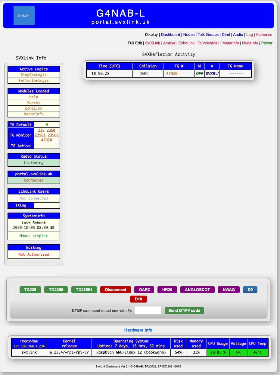
This is an example dashboard for a simplex node, but the principle is identical. Working DTMF buttons that can be edited, together with a DTMF Patch Panel. The configuration files for Svxlink, EchoLink, ModuleMetar and Node_Info can be edited on screen. Active lines have a tick, and commented out entries are unticked. In the terminal, the unused sections such as SimplexLogic if a repeater is in use can be removed entirely.
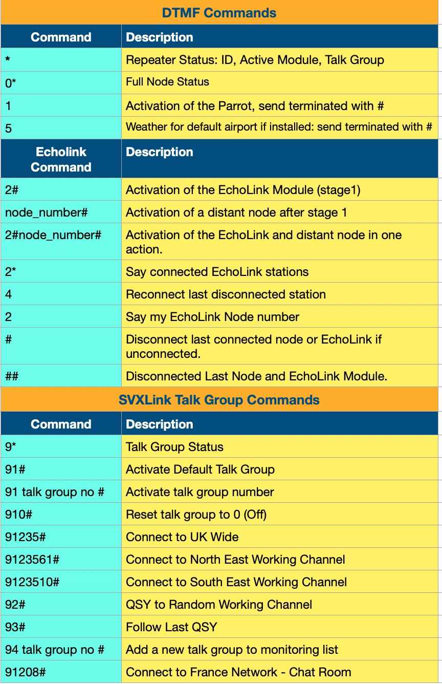
To assist with the DTMF sequences, here is a help sheet.
When devising Talkgroups, consider using an existing scheme as no doubt you might want to interact with Digital modes in the future. For example there is an existing link from the UK Reflector to Wyoming on Talkgroup 3156, a talkgroup in use on DMR already, although at this time there is not a physical link between the networks. I have tended to use the talkgroup sequences issued by BrandMeister DMR based upon the MCC. The only deviations from this are where I have used the AllStarLink Node Number.
Credits: For Tobias Blömberg SM0SVX for the continuing work on SVXLink which is the foundation of this project. To the FM-Poland team and others for inspiration on the Dashboard. To Andreas ‘Adi’ Bier DL1HRC for his other modifications to the project, such as UsrpLogic, and TetraLogic.
IMPORTANT:
This following point applies to ALL svxlink installations when you run them without Receivers Attached in a test mode.
What ever sense is applied to the SQL_GPIOD_LINE, when the svxlink is run, the sense may be opposite to that anticipated. In the case of the ICS Boards, without a receiver attached, and the correct sense applied – either Active High or Active Low the squelch in the svxlink.log will indicate OPEN. This may be counter-intuitive, but as soon as you connect the COS line of a live receiver to the port, you should find that the Squelch will close as intended, until a true signal appears. This does occur in my svxlink node, when I turn off the receiver, the SQL_GPIOD_LINE immediately detects squelch OPEN. So bear this in mind.
Chapter 2 The four port ICS 4x board.
The four channel boards are an added challenge as they will required modifying the preceding overlay codes to include the two different addresses of the MCP chips.
Firstly we modify the dts and run it as we would have done for the two port ICS card.
This is required to formulate all the required Audio Channels
sudo nano /etc/ics-repeater.dts and paste the following into the file - corrected 02-12-2026.

/dts-v1/;
/plugin/;

/ {
    compatible = "brcm,bcm2711","brcm,bcm2835";

    /* ========= Fragment 0: I2C devices ========= */
    fragment@0 {
        target = <&i2c1>;
        __overlay__ {
            status = "okay";

            #address-cells = <1>;
            #size-cells = <0>;

            /* MCP23017 @ 0x27 — core RX/TX */
            mcp26: gpio@27 {
                compatible = "microchip,mcp23017";
                reg = <0x27>;
                gpio-controller;
                #gpio-cells = <2>;
                gpio-base = <500>;

                gpio-line-names =
                    "EN_1", "EN_2", "TX_1", "TX_2",
                    "CT_1", "CT_2", "RX_1", "RX_2",
                    "EN_3", "EN_4", "TX_3", "TX_4",
                    "CT_3", "CT_4", "RX_3", "RX_4";
            };

            /* MCP23017 @ 0x26 — expansion */
            mcp27: gpio@26 {
                compatible = "microchip,mcp23017";
                reg = <0x26>;
                gpio-controller;
                #gpio-cells = <2>;
                gpio-base = <600>;

                gpio-line-names =
                    "EXP_0",  "EXP_1",  "EXP_2",  "EXP_3",
                    "EXP_4",  "EXP_5",  "EXP_6",  "EXP_7",
                    "EXP_8",  "EXP_9",  "EXP_10", "PCM_PDWN",
                    "EXP_12", "EXP_13", "EXP_14", "EXP_15";
            };

            /* ADS1015 @ 0x48 — RX */
            ads48: adc@48 {
                compatible = "ti,ads1015";
                reg = <0x48>;
                #address-cells = <1>;
                #size-cells = <0>;

                ads48_ch0: channel@0 { reg = <0>; ti,mux = <0>; ti,gain = <4>; ti,data-rate = <4>; };
                ads48_ch1: channel@1 { reg = <1>; ti,mux = <1>; ti,gain = <4>; ti,data-rate = <4>; };
                ads48_ch2: channel@2 { reg = <2>; ti,mux = <2>; ti,gain = <4>; ti,data-rate = <4>; };
                ads48_ch3: channel@3 { reg = <3>; ti,mux = <3>; ti,gain = <4>; ti,data-rate = <4>; };
            };

            /* ADS1015 @ 0x49 — TX */
            ads49: adc@49 {
                compatible = "ti,ads1015";
                reg = <0x49>;
                #address-cells = <1>;
                #size-cells = <0>;

                ads49_ch0: channel@0 { reg = <0>; ti,mux = <0>; ti,gain = <4>; ti,data-rate = <4>; };
                ads49_ch1: channel@1 { reg = <1>; ti,mux = <1>; ti,gain = <4>; ti,data-rate = <4>; };
                ads49_ch2: channel@2 { reg = <2>; ti,mux = <2>; ti,gain = <4>; ti,data-rate = <4>; };
                ads49_ch3: channel@3 { reg = <3>; ti,mux = <3>; ti,gain = <4>; ti,data-rate = <4>; };
            };

            /* SC16IS752 UART (GPS) */
            sc16: serial@4d {
                compatible = "nxp,sc16is752";
                reg = <0x4d>;
            };
        };
    };

    /* ========= Fragment 1: Aliases ========= */
    fragment@1 {
        target-path = "/";
        __overlay__ {
            aliases {
                adc-rx1 = &ads48_ch0;
                adc-rx2 = &ads48_ch1;
                adc-rx3 = &ads48_ch2;
                adc-rx4 = &ads48_ch3;

                adc-tx1 = &ads49_ch0;
                adc-tx2 = &ads49_ch1;
                adc-tx3 = &ads49_ch2;
                adc-tx4 = &ads49_ch3;
            };
        };
    };
};


Save this file as ics-repeater.dts
sudo dtc -@ -I dts -O dtb -o ics-repeater.dtbo /etc/ics-repeater.dts
sudo cp ics-repeater.dtbo /boot/firmware/overlays/sudo /boot/firmware/config.txt - and paste the following two lines at the bottom of the file and save it.
# ICS-4x Required Drivers/Overlays
dtoverlay=ics-repeater
Now sudo rebootNow we are ready to use the ports as previously however there are some number changes for the PTT SQL/COS. In the settings on a repeater card on which I am currently working, the command sudo gpioinfo shows our GPIOD lines to be all on gpiochip3 for the GPIOD settings in svxlink.conf. Fortunately with libgpiod2 we have some new bash command to view the GPIO Pins: sudo gpioinfo gpiochip2 && sudo gpioinfo gpiochip3 produces this output. The other two commands are gpioget and gpioset, which we can use later.
gpiochip2 - 16 lines:
line   0:       "EN_1"       unused   input  active-high
line   1:       "EN_2"       unused   input  active-high
line   2:       "TX_1"       unused   input  active-high
line   3:       "TX_2"       unused   input  active-high
line   4:       "CT_1"       unused   input  active-high
line   5:       "CT_2"       unused   input  active-high
line   6:       "RX_1"       unused   input  active-high
line   7:       "RX_2"       unused   input  active-high
line   8:       "EN_3"       unused   input  active-high
line   9:       "EN_4"       unused   input  active-high
line  10:       "TX_3"       unused   input  active-high
line  11:       "TX_4"       unused   input  active-high
line  12:       "CT_3"       unused   input  active-high
line  13:       "CT_4"       unused   input  active-high
line  14:       "RX_3"       unused   input  active-high
line  15:       "RX_4"       unused   input  active-high
gpiochip3 - 16 lines:
line   0:      "EXP_0"       unused   input  active-high
line   1:      "EXP_1"       unused   input  active-high
line   2:      "EXP_2"       unused   input  active-high
line   3:      "EXP_3"       unused   input  active-high
line   4:      "EXP_4"       unused   input  active-high
line   5:      "EXP_5"       unused   input  active-high
line   6:      "EXP_6"       unused   input  active-high
line   7:      "EXP_7"       unused   input  active-high
line   8:      "EXP_8"       unused   input  active-high
line   9:      "EXP_9"       unused   input  active-high
line  10:     "EXP_10"       unused   input  active-high
line  11:     "PCM_PDWN"       unused   input  active-high
line  12:     "EXP_12"       unused   input  active-high
line  13:     "EXP_13"       unused   input  active-high
line  14:     "EXP_14"       unused   input  active-high
line  15:     "EXP_15"       unused   input  active-high
We now have two additional transceivers to control numbered 0 through 3, with the SQL (RX) and PTT (TX) pins very identifiable.
Naturally this means changes to the audio ports, and I have yet to configure how this is achieved exactly, but the cat /proc/asound/cards0/stream0 provides us with all the information to produce and entirely new asound.conf for the 4-port configuration, however it will be some sorting of what audio ports go with what repeater channel. This will become apparent when we move to the next testing phase. The AtoD chips have to be turned on using one or two of the extended GPIO pins above “EXT_#”. However the below will define the alsa ports, when the audio cards have been configured.
############################
# Physical TosLink device
############################

pcm.toslink_hw {
    type hw
    card TosLink
    device 0
}

############################
# RX capture (shared)
############################

pcm.rx_capture {
    type dsnoop
    ipc_key 567890
    ipc_perm 0666
    slave {
        pcm "hw:CARD=TosLink,DEV=0"
        channels 10
        rate 48000
        format S32_LE
    }
}

pcm.rx1 {
    type plug
    slave.pcm {
        type route
        slave.pcm "rx_capture"
        slave.channels 10
        ttable { 0.0 1 }
    }
}

pcm.rx2 {
    type plug
    slave.pcm {
        type route
        slave.pcm "rx_capture"
        slave.channels 10
        ttable { 1.0 1 }
    }
}

pcm.rx3 {
    type plug
    slave.pcm {
        type route
        slave.pcm "rx_capture"
        slave.channels 10
        ttable { 2.0 1 }
    }
}

pcm.rx4 {
    type plug
    slave.pcm {
        type route
        slave.pcm "rx_capture"
        slave.channels 10
        ttable { 3.0 1 }
    }
}

############################
# TX playback (shared)
############################

pcm.tx_playback {
    type dmix
    ipc_key 678901
    ipc_perm 0666
    slave {
        pcm "hw:CARD=TosLink,DEV=0"
        channels 10
        rate 48000
        format S32_LE
    }
}

pcm.tx1 {
    type plug
    slave.pcm {
        type route
        slave.pcm "tx_playback"
        slave.channels 10
        ttable { 4.0 1 }
    }
}

pcm.tx2 {
    type plug
    slave.pcm {
        type route
        slave.pcm "tx_playback"
        slave.channels 10
        ttable { 5.0 1 }
    }
}

pcm.tx3 {
    type plug
    slave.pcm {
        type route
        slave.pcm "tx_playback"
        slave.channels 10
        ttable { 6.0 1 }
    }
}

pcm.tx4 {
    type plug
    slave.pcm {
        type route
        slave.pcm "tx_playback"
        slave.channels 10
        ttable { 7.0 1 }
    }
}
Next we need to adjust svxlink.conf to accept these pins according to the devices we are using, so two repeaters and two simplex channels are to be shown. The svxlink.conf does look a little unwieldy at this stagem and when run will display alsa warnings in the log as to the use of dsnoop and dmix but this is perfectly normal and with adjustment can be masked.
The GPIO Pins are named from the DTS set in the /boot/firmware/config.txt
so we can ignore numbers and work directly with the text - RX_1 - RX_4 and TX_1 - TX_4 according to numeration protocol and fit the channels 1, 2, 3 and 4 in the following configuration.

This have to be set in svxlink.conf, with copies of Rx1 - 4 and Tx1 to 4
and where necessary copying [RepeaterLogic(1-2) and SimplexLogic(3-4)] here and in the .tcl folder in the deeper logic.

In this board we have a reset pin PCM_PDWN that we have to control with a short python script. This enables the ADC sound chips

The first course of action if not already done, is to enable the second part of the serial port in sudo raspi-config, and reboot.
On rentering the terminal discover the which port is now the serial port to the ICS card, not the i2c port. At the prompt type ls -l /dev/serial*
This will return the configure port, usually as a symlink.
ls -l /dev/serial*
lrwxrwxrwx 1 root root 7 Jan 23 08:29 /dev/serial0 -> ttyAMA0

Now we can create our python scripts. We can add this to a cronjob to ensure the soundcard starts at boot before the svxlink.service begins.

#!/usr/bin/env python3

import gpiod
import time

CHIP = "gpiochip3"
LINE = 11

chip = gpiod.chip(CHIP)
line = chip.get_line(LINE)

line.request(
    consumer="ads1015-enable",
    type=gpiod.LINE_REQ_DIR_OUT,
    default_vals=[1]   # HIGH = ADC enabled
)

print("ADS1015 enabled (GPIO HIGH)")

chip.close()


An alternative method to activate a gpio port is the use of the gpioget and the gpioset command: for example -
sudo gpioget gpiochip0 23 will return the current value of that GPIO port.
sudo gpioset gpiochip3 GPIO506=1 or (sudo gpioset gpiochip3 10=1) will set the value as high.
So if using the python code we set the GPIO607 as Output and set it as active low, we can facilitate the reset by momentarily setting it to 1 to place the 3.3 volt action to reset the chip.

Ignore any reference in the ICS instructions setting gpio.conf as this is now deprecated in libgpiod.
Completing the configuration.
Finally a completed svxlink.conf with the password for the reflector masked.

##############################################################
#                                                                             #
#                Configuration file for the SvxLink server                    #
#                                                                             #
##############################################################

[GLOBAL]
#MODULE_PATH=/usr/lib/arm-linux-gnueabihf/svxlink
LOGIC_CORE_PATH=/usr/lib/arm-linux-gnueabihf/svxlink
LOGICS=Repeater1Logic,Repeater2Logic,ReflectorLogic,Simplex3Logic,Simplex4Logic
CFG_DIR=svxlink.d
TIMESTAMP_FORMAT="%c"
CARD_SAMPLE_RATE=48000
CARD_CHANNELS=2
#LOCATION_INFO=LocationInfo
LINKS=LinkToReflector

[Repeater1Logic]
TYPE=Repeater
RX=Rx1
TX=Tx1
MODULES=ModuleHelp,ModuleParrot,ModuleMetarInfo
CALLSIGN=AK6BL
##
SHORT_IDENT_INTERVAL=10
SHORT_VOICE_ID_ENABLE=0
SHORT_CW_ID_ENABLE=1
SHORT_ANNOUNCE_ENABLE=0
SHORT_ANNOUNCE_FILE = ""
##
LONG_IDENT_INTERVAL=0
LONG_VOICE_ID_ENABLE=0
LONG_CW_ID_ENABLE=1
LONG_ANNOUNCE_ENABLE=0
LONG_ANNOUNCE_FILE = ""
##
TIME_FORMAT="24"
CW_AMP=-10
CW_PITCH=650
CW_CPM=120
#IDENT_ONLY_AFTER_TX=4
#EXEC_CMD_ON_SQL_CLOSE=500
EVENT_HANDLER=/usr/share/svxlink/events.tcl
DEFAULT_LANG=en_US
RGR_SOUND_DELAY=0
#REPORT_CTCSS=136.5
#TX_CTCSS=SQL_OPEN
MACROS=Macros
#SEL5_MACRO_RANGE=03400,03499
FX_GAIN_NORMAL=0
FX_GAIN_LOW=-12
#QSO_RECORDER=8:QsoRecorder
#NO_REPEAT=1
IDLE_TIMEOUT=7
OPEN_ON_1750=800
#OPEN_ON_CTCSS=1000
#OPEN_ON_DTMF=*
OPEN_ON_SQL=200
#OPEN_ON_SEL5=01234
OPEN_SQL_FLANK=OPEN
#OPEN_ON_SQL_AFTER_RPT_CLOSE=10
IDLE_SOUND_INTERVAL=3000
#SQL_FLAP_SUP_MIN_TIME=1000
#SQL_FLAP_SUP_MAX_COUNT=10
SQL_TIMEOUT=180
#ACTIVATE_MODULE_ON_LONG_CMD=4:EchoLink
#IDENT_NAG_TIMEOUT=15
#IDENT_NAG_MIN_TIME=2000
#ONLINE_CMD=998877
#ONLINE=1
#STATE_PTY=/var/run/svxlink/state
[Repeater2Logic]
TYPE=Repeater
RX=Rx2
TX=Tx2
MODULES=ModuleHelp,ModuleParrot,ModuleMetarInfo
CALLSIGN=AK6BL
##
SHORT_IDENT_INTERVAL=10
SHORT_VOICE_ID_ENABLE=0
SHORT_CW_ID_ENABLE=1
SHORT_ANNOUNCE_ENABLE=0
SHORT_ANNOUNCE_FILE = ""
##
LONG_IDENT_INTERVAL=0
LONG_VOICE_ID_ENABLE=0
LONG_CW_ID_ENABLE=1
LONG_ANNOUNCE_ENABLE=0
LONG_ANNOUNCE_FILE = ""
##
TIME_FORMAT="24"
CW_AMP=-10
CW_PITCH=650
CW_CPM=120
#IDENT_ONLY_AFTER_TX=4
#EXEC_CMD_ON_SQL_CLOSE=500
EVENT_HANDLER=/usr/share/svxlink/events.tcl
DEFAULT_LANG=en_US
RGR_SOUND_DELAY=0
#REPORT_CTCSS=136.5
#TX_CTCSS=SQL_OPEN
MACROS=Macros
#SEL5_MACRO_RANGE=03400,03499
FX_GAIN_NORMAL=0
FX_GAIN_LOW=-12
#QSO_RECORDER=8:QsoRecorder
#NO_REPEAT=1
IDLE_TIMEOUT=7
OPEN_ON_1750=800
#OPEN_ON_CTCSS=1000
#OPEN_ON_DTMF=*
OPEN_ON_SQL=200
#OPEN_ON_SEL5=01234
OPEN_SQL_FLANK=OPEN
#OPEN_ON_SQL_AFTER_RPT_CLOSE=10
IDLE_SOUND_INTERVAL=3000
#SQL_FLAP_SUP_MIN_TIME=1000
#SQL_FLAP_SUP_MAX_COUNT=10
SQL_TIMEOUT=180
#ACTIVATE_MODULE_ON_LONG_CMD=4:EchoLink
#IDENT_NAG_TIMEOUT=15
#IDENT_NAG_MIN_TIME=2000
#ONLINE_CMD=998877
#ONLINE=1
#STATE_PTY=/var/run/svxlink/state
DTMF_CTRL_PTY=/var/run/svxlink/dtmf_svx
#DTMF_IGNORE_WHEN_NOT_UP=1
#CTCSS_TO_TG=77.0:999,123.0:9990,146.2:9992
#CTCSS_TO_TG_DELAY=0
DTMF_CTRL_PTY=/var/run/svxlink/dtmf_svx
#DTMF_IGNORE_WHEN_NOT_UP=1
#CTCSS_TO_TG=77.0:999,123.0:9990,146.2:9992
#CTCSS_TO_TG_DELAY=0

[Simplex3Logic]
TYPE=Simplex
RX=Rx3
TX=Tx3
MODULES=ModuleHelp,ModuleParrot,ModuleMetarInfo
CALLSIGN=AK6BL
#
SHORT_IDENT_INTERVAL=15
SHORT_VOICE_ID_ENABLE=0
SHORT_CW_ID_ENABLE=1
SHORT_ANNOUNCE_ENABLE=0
SHORT_ANNOUNCE_FILE = ""
##
LONG_IDENT_INTERVAL=60
LONG_VOICE_ID_ENABLE=1
LONG_CW_ID_ENABLE=0
LONG_ANNOUNCE_ENABLE=0
LONG_ANNOUNCE_FILE = ""
##
TIME_FORMAT="24"
CW_AMP = -10
CW_PITCH = 650
CW_CPM = 95
#IDENT_ONLY_AFTER_TX=4
#EXEC_CMD_ON_SQL_CLOSE=500
EVENT_HANDLER=/usr/share/svxlink/events.tcl
DEFAULT_LANG=en_GB
RGR_SOUND_DELAY=0
RGR_SOUND_ALWAYS=1
#REPORT_CTCSS=136.5
#TX_CTCSS=ALWAYS
MACROS=Macros
FX_GAIN_NORMAL=0
FX_GAIN_LOW=-12
#ACTIVATE_MODULE_ON_LONG_CMD=4:EchoLink
#QSO_RECORDER=8:QsoRecorder
#ONLINE_CMD=998877
#ONLINE=1
MUTE_RX_ON_TX=1
MUTE_TX_ON_RX=1
#STATE_PTY=/var/run/svxlink/state
DTMF_CTRL_PTY=/var/run/svxlink/dtmf_svx
#CTCSS_TO_TG=77.0:999,123.0:9990,146.2:9992
#CTCSS_TO_TG_DELAY=1000

[Simplex4Logic]
TYPE=Simplex
RX=Rx4
TX=Tx4
MODULES=ModuleHelp,ModuleParrot,ModuleMetarInfo
CALLSIGN=AK6BL
#
SHORT_IDENT_INTERVAL=15
SHORT_VOICE_ID_ENABLE=0
SHORT_CW_ID_ENABLE=1
SHORT_ANNOUNCE_ENABLE=0
SHORT_ANNOUNCE_FILE = ""
##
LONG_IDENT_INTERVAL=60
LONG_VOICE_ID_ENABLE=1
LONG_CW_ID_ENABLE=0
LONG_ANNOUNCE_ENABLE=0
LONG_ANNOUNCE_FILE = ""
##
TIME_FORMAT="24"
CW_AMP = -10
CW_PITCH = 650
CW_CPM = 95
#IDENT_ONLY_AFTER_TX=4
#EXEC_CMD_ON_SQL_CLOSE=500
EVENT_HANDLER=/usr/share/svxlink/events.tcl
DEFAULT_LANG=en_GB
RGR_SOUND_DELAY=0
RGR_SOUND_ALWAYS=1
#REPORT_CTCSS=136.5
#TX_CTCSS=ALWAYS
MACROS=Macros
FX_GAIN_NORMAL=0
FX_GAIN_LOW=-12
#ACTIVATE_MODULE_ON_LONG_CMD=4:EchoLink
#QSO_RECORDER=8:QsoRecorder
#ONLINE_CMD=998877
#ONLINE=1
MUTE_RX_ON_TX=1
MUTE_TX_ON_RX=1
#STATE_PTY=/var/run/svxlink/state
DTMF_CTRL_PTY=/var/run/svxlink/dtmf_svx
#CTCSS_TO_TG=77.0:999,123.0:9990,146.2:9992
#CTCSS_TO_TG_DELAY=1000

[ReflectorLogic]
TYPE=ReflectorV2
#DNS_DOMAIN=example.com
HOSTS=@.@.@.@
HOST_PORT=#####
HOST_PRIO=100
HOST_PRIO_INC=1
HOST_WEIGHT=10
CALLSIGN="AK6BL"
#CERT_PKI_DIR="/var/lib/svxlink/pki"
#CERT_KEYFILE=/var/lib/svxlink/pki/AK6BL.key
#CERT_CSRFILE=/var/lib/svxlink/pki/AK6BL.csr
#CERT_CRTFILE=/var/lib/svxlink/pki/AK6BL.crt
#CERT_CAFILE=/var/lib/svxlink/pki/ca-bundle.pem
#CERT_DOWNLOAD_CA_BUNDLE=1
#CERT_SUBJ_givenName=John
#CERT_SUBJ_surname=Doe
#CERT_SUBJ_organizationalUnitName=SvxLink
#CERT_SUBJ_organizationName=SSA
#CERT_SUBJ_localityName=Stockholm
#CERT_SUBJ_stateOrProvinceName=Södermanland
#CERT_SUBJ_countryName=SE
#[email protected]
AUTH_KEY="masked"
JITTER_BUFFER_DELAY=0
DEFAULT_TG=0
MONITOR_TGS=235
TG_SELECT_TIMEOUT=30
TG_SELECT_INHIBIT_TIMEOUT=0
ANNOUNCE_REMOTE_MIN_INTERVAL=300
EVENT_HANDLER=/usr/share/svxlink/events.tcl
NODE_INFO_FILE=/etc/svxlink/node_info.json
MUTE_FIRST_TX_LOC=0
MUTE_FIRST_TX_REM=0
#TMP_MONITOR_TIMEOUT=3600
UDP_HEARTBEAT_INTERVAL=15
QSY_PENDING_TIMEOUT=15
DEFAULT_LANG=en_US
#VERBOSE=1

[LinkToReflector]
CONNECT_LOGICS=RepeaterLogic:9:,Repeater2Logic:9:,SimplexLogic:9:,Simplex2Logic:9:,ReflectorLogic
DEFAULT_ACTIVE=1
OPTIONS = DEFAULT_CONNECT,NO_DISCONNECT
TIMEOUT=300
#ACTIVATE_ON_ACTIVITY=RepeaterLogic

[Macros]
1=::91235#
2=::912350#
6=::9123561#
9=::910#

[QsoRecorder]
REC_DIR=/var/spool/svxlink/qso_recorder
#MIN_TIME=1000
MAX_TIME=3600
SOFT_TIME=300
MAX_DIRSIZE=1024
#DEFAULT_ACTIVE=1
#TIMEOUT=300
#QSO_TIMEOUT=300
#ENCODER_CMD=/usr/bin/oggenc -Q \"%f\" && rm \"%f\"

[Voter]
TYPE=Voter
RECEIVERS=Rx1,Rx2,Rx3
VOTING_DELAY=200
BUFFER_LENGTH=0
#REVOTE_INTERVAL=1000
#HYSTERESIS=50
#SQL_CLOSE_REVOTE_DELAY=500
#RX_SWITCH_DELAY=500
#COMMAND_PTY=/dev/shm/voter_ctrl
#VERBOSE=1

[MultiTx]
TYPE=Multi
TRANSMITTERS=Tx1,TxStream

[TxStream]
TYPE = Local
AUDIO_DEV = alsa:plughw:Loopback,0,0
AUDIO_CHANNEL = 0
PTT_TYPE = NONE
TIMEOUT = 7200
TX_DELAY = 0
PREEMPHASIS = 0

[NetRx]
TYPE=Net
HOST=remote.rx.host
TCP_PORT=5210
#LOG_DISCONNECTS_ONCE=0
AUTH_KEY=""
CODEC=S16
#SPEEX_ENC_FRAMES_PER_PACKET=4
#SPEEX_ENC_QUALITY=4
#SPEEX_ENC_BITRATE=15000
#SPEEX_ENC_COMPLEXITY=2
#SPEEX_ENC_VBR=0
#SPEEX_ENC_VBR_QUALITY=4
#SPEEX_ENC_ABR=15000
#SPEEX_DEC_ENHANCER=1
#OPUS_ENC_FRAME_SIZE=20
#OPUS_ENC_COMPLEXITY=10
#OPUS_ENC_BITRATE=20000
#OPUS_ENC_VBR=1

[NetTx]
TYPE=Net
#TX_ID=T
HOST=remote.tx.host
TCP_PORT=5210
#LOG_DISCONNECTS_ONCE=0
AUTH_KEY=""
CODEC=S16
#SPEEX_ENC_FRAMES_PER_PACKET=4
#SPEEX_ENC_QUALITY=4
#SPEEX_ENC_BITRATE=15000
#SPEEX_ENC_COMPLEXITY=2
#SPEEX_ENC_VBR=0
#SPEEX_ENC_VBR_QUALITY=4
#SPEEX_ENC_ABR=15000
#SPEEX_DEC_ENHANCER=1
#OPUS_ENC_FRAME_SIZE=20
#OPUS_ENC_COMPLEXITY=10
#OPUS_ENC_BITRATE=20000
#OPUS_ENC_VBR=1
## Port1 ##
[Rx1]
TYPE=Local
#RX_ID=?
AUDIO_DEV=alsa:rx1
AUDIO_CHANNEL=0
#AUDIO_DEV_KEEP_OPEN=0
#LIMITER_THRESH=-6
SQL_DET=GPIOD
SQL_START_DELAY=0
SQL_DELAY=0
SQL_HANGTIME=10
#SQL_EXTENDED_HANGTIME=1000
#SQL_EXTENDED_HANGTIME_THRESH=15
#SQL_TIMEOUT=600
#VOX_FILTER_DEPTH=20
#VOX_THRESH=1000
#CTCSS_MODE=2
#CTCSS_FQ=136.5
#CTCSS_SNR_OFFSET=0
#CTCSS_SNR_OFFSETS=88.5:-1.0,136.5:-0.5
#CTCSS_OPEN_THRESH=15
#CTCSS_CLOSE_THRESH=9
#CTCSS_BPF_LOW=60
#CTCSS_BPF_HIGH=270
#CTCSS_EMIT_TONE_DETECTED=0
#SERIAL_PORT=/dev/ttyS0
#SERIAL_PIN=CTS
#SERIAL_SET_PINS=DTR!RTS
#EVDEV_DEVNAME=/dev/input/by-id/usb-SYNIC_SYNIC_Wireless_Audio-event-if03
#EVDEV_OPEN=1,163,1
#EVDEV_CLOSE=1,163,0
#GPIO_PATH=/sys/class/gpio
#GPIO_SQL_PIN=gpio30
SQL_GPIOD_CHIP=gpiochip2
SQL_GPIOD_LINE=RX_1
#SQL_GPIOD_BIAS=PULLDOWN
#PTY_PATH=/tmp/rx1_sql
#HID_DEVICE=/dev/hidraw0
#HID_SQL_PIN=VOL_DN
#SIGLEV_DET=TONE
#SIGLEV_SLOPE=1
#SIGLEV_OFFSET=0
#SIGLEV_BOGUS_THRESH=120
#TONE_SIGLEV_MAP=100,84,60,50,37,32,28,23,19,8
#SQL_SIGLEV_OPEN_THRESH=30
#SQL_SIGLEV_CLOSE_THRESH=10
DEEMPHASIS=0
SQL_TAIL_ELIM=270
#PREAMP=6
PEAK_METER=0
DTMF_DEC_TYPE=INTERNAL
DTMF_MUTING=1
#DTMF_HANGTIME=40
#DTMF_SERIAL=/dev/ttyS0
#DTMF_PTY=/tmp/rx1_dtmf
#DTMF_MAX_FWD_TWIST=8
#DTMF_MAX_REV_TWIST=4
#1750_MUTING=1
#SEL5_DEC_TYPE=INTERNAL
#SEL5_TYPE=ZVEI1
#FQ=433475000
#MODULATION=FM
#WBRX=WbRx1
#OB_AFSK_ENABLE=0
#OB_AFSK_VOICE_GAIN=6
#IB_AFSK_ENABLE=0
#LADSPA_PLUGINS=hpf:1000,@Rx1_Compressor

##Port2##
[Rx2]
TYPE=Local
#RX_ID=?
AUDIO_DEV=alsa:rx2
AUDIO_CHANNEL=0
#AUDIO_DEV_KEEP_OPEN=0
#LIMITER_THRESH=-6
SQL_DET=GPIOD
SQL_START_DELAY=0
SQL_DELAY=0
SQL_HANGTIME=20
#SQL_EXTENDED_HANGTIME=1000
#SQL_EXTENDED_HANGTIME_THRESH=15
#SQL_TIMEOUT=600
#VOX_FILTER_DEPTH=20
#VOX_THRESH=1000
#CTCSS_MODE=2
#CTCSS_FQ=136.5
#CTCSS_SNR_OFFSET=0
#CTCSS_SNR_OFFSETS=88.5:-1.0,136.5:-0.5
#CTCSS_OPEN_THRESH=15
#CTCSS_CLOSE_THRESH=9
#CTCSS_BPF_LOW=60
#CTCSS_BPF_HIGH=270
#CTCSS_EMIT_TONE_DETECTED=0
#SERIAL_PORT=/dev/ttyS0
#SERIAL_PIN=CTS
#SERIAL_SET_PINS=DTR!RTS
#EVDEV_DEVNAME=/dev/input/by-id/usb-SYNIC_SYNIC_Wireless_Audio-event-if03
#EVDEV_OPEN=1,163,1
#EVDEV_CLOSE=1,163,0
#GPIO_PATH=/sys/class/gpio
#GPIO_SQL_PIN=gpio30
SQL_GPIOD_CHIP=gpiochip2
SQL_GPIOD_LINE=RX_2
#SQL_GPIOD_BIAS=PULLDOWN
#PTY_PATH=/tmp/rx1_sql
#HID_DEVICE=/dev/hidraw0
#HID_SQL_PIN=VOL_DN
#SIGLEV_DET=TONE
#SIGLEV_SLOPE=1
#SIGLEV_OFFSET=0
#SIGLEV_BOGUS_THRESH=120
#TONE_SIGLEV_MAP=100,84,60,50,37,32,28,23,19,8
#SQL_SIGLEV_OPEN_THRESH=30
#SQL_SIGLEV_CLOSE_THRESH=10
DEEMPHASIS=0
SQL_TAIL_ELIM=270
#PREAMP=6
PEAK_METER=1
DTMF_DEC_TYPE=INTERNAL
DTMF_MUTING=1
#DTMF_HANGTIME=40
#DTMF_SERIAL=/dev/ttyS0
#DTMF_PTY=/tmp/rx1_dtmf
#DTMF_MAX_FWD_TWIST=8
#DTMF_MAX_REV_TWIST=4
#1750_MUTING=1
#SEL5_DEC_TYPE=INTERNAL
#SEL5_TYPE=ZVEI1
#FQ=433475000
#MODULATION=FM
#WBRX=WbRx1
#OB_AFSK_ENABLE=0
#OB_AFSK_VOICE_GAIN=6
#IB_AFSK_ENABLE=0
#LADSPA_PLUGINS=hpf:1000,@Rx1_Compressor

##Port3##
[Rx3]
TYPE=Local
#RX_ID=?
AUDIO_DEV=alsa:rx3
AUDIO_CHANNEL=0
#AUDIO_DEV_KEEP_OPEN=0
#LIMITER_THRESH=-6
SQL_DET=GPIOD
SQL_START_DELAY=0
SQL_DELAY=0
SQL_HANGTIME=20
#SQL_EXTENDED_HANGTIME=1000
#SQL_EXTENDED_HANGTIME_THRESH=15
#SQL_TIMEOUT=600
#VOX_FILTER_DEPTH=20
#VOX_THRESH=1000
#CTCSS_MODE=2
#CTCSS_FQ=136.5
#CTCSS_SNR_OFFSET=0
#CTCSS_SNR_OFFSETS=88.5:-1.0,136.5:-0.5
#CTCSS_OPEN_THRESH=15
#CTCSS_CLOSE_THRESH=9
#CTCSS_BPF_LOW=60
#CTCSS_BPF_HIGH=270
#CTCSS_EMIT_TONE_DETECTED=0
#SERIAL_PORT=/dev/ttyS0
#SERIAL_PIN=CTS
#SERIAL_SET_PINS=DTR!RTS
#EVDEV_DEVNAME=/dev/input/by-id/usb-SYNIC_SYNIC_Wireless_Audio-event-if03
#EVDEV_OPEN=1,163,1
#EVDEV_CLOSE=1,163,0
#GPIO_PATH=/sys/class/gpio
#GPIO_SQL_PIN=gpio30
SQL_GPIOD_CHIP=gpiochip2
SQL_GPIOD_LINE=RX_3
#SQL_GPIOD_BIAS=PULLDOWN
#PTY_PATH=/tmp/rx1_sql
#HID_DEVICE=/dev/hidraw0
#HID_SQL_PIN=VOL_DN
#SIGLEV_DET=TONE
#SIGLEV_SLOPE=1
#SIGLEV_OFFSET=0
#SIGLEV_BOGUS_THRESH=120
#TONE_SIGLEV_MAP=100,84,60,50,37,32,28,23,19,8
#SQL_SIGLEV_OPEN_THRESH=30
#SQL_SIGLEV_CLOSE_THRESH=10
DEEMPHASIS=0
SQL_TAIL_ELIM=270
#PREAMP=6
PEAK_METER=1
DTMF_DEC_TYPE=INTERNAL
DTMF_MUTING=1
#DTMF_HANGTIME=40
#DTMF_SERIAL=/dev/ttyS0
#DTMF_PTY=/tmp/rx1_dtmf
#DTMF_MAX_FWD_TWIST=8
#DTMF_MAX_REV_TWIST=4
#1750_MUTING=1
#SEL5_DEC_TYPE=INTERNAL
#SEL5_TYPE=ZVEI1
#FQ=433475000
#MODULATION=FM
#WBRX=WbRx1
#OB_AFSK_ENABLE=0
#OB_AFSK_VOICE_GAIN=6
#IB_AFSK_ENABLE=0
#LADSPA_PLUGINS=hpf:1000,@Rx1_Compressor

##Port4##
[Rx4]
TYPE=Local
#RX_ID=?
AUDIO_DEV=alsa:rx4
AUDIO_CHANNEL=0
#AUDIO_DEV_KEEP_OPEN=0
#LIMITER_THRESH=-6
SQL_DET=GPIOD
SQL_START_DELAY=0
SQL_DELAY=0
SQL_HANGTIME=20
#SQL_EXTENDED_HANGTIME=1000
#SQL_EXTENDED_HANGTIME_THRESH=15
#SQL_TIMEOUT=600
#VOX_FILTER_DEPTH=20
#VOX_THRESH=1000
#CTCSS_MODE=2
#CTCSS_FQ=136.5
#CTCSS_SNR_OFFSET=0
#CTCSS_SNR_OFFSETS=88.5:-1.0,136.5:-0.5
#CTCSS_OPEN_THRESH=15
#CTCSS_CLOSE_THRESH=9
#CTCSS_BPF_LOW=60
#CTCSS_BPF_HIGH=270
#CTCSS_EMIT_TONE_DETECTED=0
#SERIAL_PORT=/dev/ttyS0
#SERIAL_PIN=CTS
#SERIAL_SET_PINS=DTR!RTS
#EVDEV_DEVNAME=/dev/input/by-id/usb-SYNIC_SYNIC_Wireless_Audio-event-if03
#EVDEV_OPEN=1,163,1
#EVDEV_CLOSE=1,163,0
#GPIO_PATH=/sys/class/gpio
#GPIO_SQL_PIN=gpio30
SQL_GPIOD_CHIP=gpiochip2
SQL_GPIOD_LINE=RX_4
#SQL_GPIOD_BIAS=PULLDOWN
#PTY_PATH=/tmp/rx1_sql
#HID_DEVICE=/dev/hidraw0
#HID_SQL_PIN=VOL_DN
#SIGLEV_DET=TONE
#SIGLEV_SLOPE=1
#SIGLEV_OFFSET=0
#SIGLEV_BOGUS_THRESH=120
#TONE_SIGLEV_MAP=100,84,60,50,37,32,28,23,19,8
#SQL_SIGLEV_OPEN_THRESH=30
#SQL_SIGLEV_CLOSE_THRESH=10
DEEMPHASIS=0
SQL_TAIL_ELIM=270
#PREAMP=6
PEAK_METER=1
DTMF_DEC_TYPE=INTERNAL
DTMF_MUTING=1
#DTMF_HANGTIME=40
#DTMF_SERIAL=/dev/ttyS0
#DTMF_PTY=/tmp/rx1_dtmf
#DTMF_MAX_FWD_TWIST=8
#DTMF_MAX_REV_TWIST=4
#1750_MUTING=1
#SEL5_DEC_TYPE=INTERNAL
#SEL5_TYPE=ZVEI1
#FQ=433475000
#MODULATION=FM
#WBRX=WbRx1
#OB_AFSK_ENABLE=0
#OB_AFSK_VOICE_GAIN=6
#IB_AFSK_ENABLE=0
#LADSPA_PLUGINS=hpf:1000,@Rx1_Compressor

[Rx1_Compressor]
#LABEL=tap_dynamics_m
#Attack=4
#Release=500
#Offset Gain=15
#Makeup Gain=15
#Function=13

[WbRx1]
#TYPE=RtlUsb
#DEV_MATCH=0
#HOST=localhost
#PORT=1234
#CENTER_FQ=435075000
#FQ_CORR=0
#GAIN=0
#PEAK_METER=0
#SAMPLE_RATE=960000

[DevcalRtlRx]
TYPE=Ddr
WBRX=WbRx1
FQ=145700000

##Port1##
[Tx1]
TYPE=Local
#TX_ID=T
AUDIO_DEV=alsa:tx1
AUDIO_CHANNEL=0
#AUDIO_DEV_KEEP_OPEN=0
#LIMITER_THRESH=-6
PTT_TYPE=GPIOD
#PTT_PORT=/dev/ttyS0
#PTT_PIN=DTRRTS
#HID_DEVICE=/dev/hidraw0
#HID_PTT_PIN=GPIO3
#SERIAL_SET_PINS=DTR!RTS
#GPIO_PATH=/sys/class/gpio
PTT_GPIOD_CHIP=gpiochip2
PTT_GPIOD_LINE=!TX_1
#PTT_HANGTIME=1000
#TIMEOUT=300
#TX_DELAY=500
#CTCSS_FQ=136.5
#CTCSS_LEVEL=-24
#PREEMPHASIS=0
#DTMF_TONE_LENGTH=100
#DTMF_TONE_SPACING=50
#DTMF_DIGIT_PWR=-15
#MASTER_GAIN=0.0
#OB_AFSK_ENABLE=0
#OB_AFSK_VOICE_GAIN=-6
#OB_AFSK_LEVEL=-12
#OB_AFSK_TX_DELAY=100
#IB_AFSK_ENABLE=0
#IB_AFSK_LEVEL=-6
#IB_AFSK_TX_DELAY=100
#LADSPA_PLUGINS=hpf:1000,@Tx1_Compressor

##Port2##
[Tx2]
TYPE=Local
#TX_ID=T
AUDIO_DEV=alsa:tx2
AUDIO_CHANNEL=0
#AUDIO_DEV_KEEP_OPEN=0
#LIMITER_THRESH=-6
PTT_TYPE=GPIOD
#PTT_PORT=/dev/ttyS0
#PTT_PIN=DTRRTS
#HID_DEVICE=/dev/hidraw0
#HID_PTT_PIN=GPIO3
#SERIAL_SET_PINS=DTR!RTS
#GPIO_PATH=/sys/class/gpio
PTT_GPIOD_CHIP=gpiochip2
PTT_GPIOD_LINE=!TX_2
#PTT_HANGTIME=1000
#TIMEOUT=300
#TX_DELAY=500
#CTCSS_FQ=136.5
#CTCSS_LEVEL=-24
#PREEMPHASIS=0
#DTMF_TONE_LENGTH=100
#DTMF_TONE_SPACING=50
#DTMF_DIGIT_PWR=-15
#MASTER_GAIN=0.0
#OB_AFSK_ENABLE=0
#OB_AFSK_VOICE_GAIN=-6
#OB_AFSK_LEVEL=-12
#OB_AFSK_TX_DELAY=100
#IB_AFSK_ENABLE=0
#IB_AFSK_LEVEL=-6
#IB_AFSK_TX_DELAY=100
#LADSPA_PLUGINS=hpf:1000,@Tx1_Compressor

##Port3##
[Tx3]
TYPE=Local
#TX_ID=T
AUDIO_DEV=alsa:tx3
AUDIO_CHANNEL=0
#AUDIO_DEV_KEEP_OPEN=0
#LIMITER_THRESH=-6
PTT_TYPE=GPIOD
#PTT_PORT=/dev/ttyS0
#PTT_PIN=DTRRTS
#HID_DEVICE=/dev/hidraw0
#HID_PTT_PIN=GPIO3
#SERIAL_SET_PINS=DTR!RTS
#GPIO_PATH=/sys/class/gpio
PTT_GPIOD_CHIP=gpiochip2
PTT_GPIOD_LINE=!TX_3
#PTT_HANGTIME=1000
#TIMEOUT=300
#TX_DELAY=500
#CTCSS_FQ=136.5
#CTCSS_LEVEL=-24
#PREEMPHASIS=0
#DTMF_TONE_LENGTH=100
#DTMF_TONE_SPACING=50
#DTMF_DIGIT_PWR=-15
#MASTER_GAIN=0.0
#OB_AFSK_ENABLE=0
#OB_AFSK_VOICE_GAIN=-6
#OB_AFSK_LEVEL=-12
#OB_AFSK_TX_DELAY=100
#IB_AFSK_ENABLE=0
#IB_AFSK_LEVEL=-6
#IB_AFSK_TX_DELAY=100
#LADSPA_PLUGINS=hpf:1000,@Tx1_Compressor

##Port4##
[Tx4]
TYPE=Local
#TX_ID=T
AUDIO_DEV=alsa:tx4
AUDIO_CHANNEL=0
#AUDIO_DEV_KEEP_OPEN=0
#LIMITER_THRESH=-6
PTT_TYPE=GPIOD
#PTT_PORT=/dev/ttyS0
#PTT_PIN=DTRRTS
#HID_DEVICE=/dev/hidraw0
#HID_PTT_PIN=GPIO3
#SERIAL_SET_PINS=DTR!RTS
#GPIO_PATH=/sys/class/gpio
PTT_GPIOD_CHIP=gpiochip2
PTT_GPIOD_LINE=!TX_4
#PTT_HANGTIME=1000
#TIMEOUT=300
#TX_DELAY=500
#CTCSS_FQ=136.5
#CTCSS_LEVEL=-24
#PREEMPHASIS=0
#DTMF_TONE_LENGTH=100
#DTMF_TONE_SPACING=50
#DTMF_DIGIT_PWR=-15
#MASTER_GAIN=0.0
#OB_AFSK_ENABLE=0
#OB_AFSK_VOICE_GAIN=-6
#OB_AFSK_LEVEL=-12
#OB_AFSK_TX_DELAY=100
#IB_AFSK_ENABLE=0
#IB_AFSK_LEVEL=-6
#IB_AFSK_TX_DELAY=100
#LADSPA_PLUGINS=hpf:1000,@Tx1_Compressor
[Tx1_Compressor]
#LABEL=tap_dynamics_m
#Attack=4
#Release=500
#Offset Gain=15
#Makeup Gain=15
#Function=13

[LocationInfo]
CALLSIGN=OBJECT_NAME
#SOURCE_CALLSIGN=AK6BL-1
#LOGIN_CALLSIGN=AK6BL-XX
APRS_SERVER_LIST=rotate.aprs2.net:14580
#STATUS_SERVER_LIST=aprs.echolink.org:5199
#FILTER=m/10
#SYMBOL=/r
#LON_POSITION=12.10.00E
#LAT_POSITION=51.10.00N
#FREQUENCY=438.875
#FREQUENCY_SEPARATOR="/"
#TX_OFFSET=-600
#NARROW=1
#TX_POWER=8
#ANTENNA_GAIN=6
#ANTENNA_HEIGHT=20m
#ANTENNA_DIR=-1
#PATH=TCPIP*
#BEACON_INTERVAL=10
#STATISTICS_INTERVAL=10
#STATISTICS_LOGIC=SimplexLogic
#TONE=136.5
#COMMENT=SvxLink Node
#PTY_PATH=/dev/shm/aprs_pty
#DEBUG=0
The only likely changes to this file will be the sense of the PTT_GPIOD_LINE or SQ_GPIOD_LINE by adding or removing a ! preceding the pin designation.
Finally two points have come to light that may raise a couple of concerns.
- The PTT_GPIOD_LINEs may go to an unwelcome state when the svxlink.service is stopped, that might cause the transmitter(s) to activate without controls.
- You may feel that the processor load is significant high.
Dealing with the second issue first: The Svxlink Dashboard footer will show the load on the processor and will indicate around 20% which is probably about normal for this installation. Do not forget that the svxlink is a relatively light touch on the Raspberry Pi simply monitoring and controlling ports and pushing sound. The WebServer is also light in comparison. If you have concerns, then also in the footer is a link to a system dashboard at ‘Hardware Info’ where the load is further described together with all the diagnostic information for the running Pi. My svxlink node runs at .62% which is remarkably low, whereas a four port svxlink is monitoring many more ports, and driving the ICS Board as well so 26% is not to be unexpected.
Now the first issue. I offer the following solution that will overcome the unwanted PTT issue, when the svxlink.service is halted. Libgpiod2 will change the control status of the pins formerly controlled by svxlink. So we shall require these pins to be set to the opposite state of that of the PTT control.
Imagine therefore if a ptt required ACTIVE-LOW the PTT_GPIOD_LINE=!TX_0, there is a possibiity that when the svxlink.service is stopped then we will require this pin in the gpiochip to go ACTIVE HIGH to stop an unwarranted transmission by the connected transceiver on the port.
So we make a service that has a responsibility to manage this state when the svxlink.service is stopped.
We make first of all a bash script to control these ports.
sudo nano /usr/local/bin/tx-hold.sh
#!/bin/bash
# Hold TX GPIO lines inactive indefinitely (safe for libgpiod2)

CHIP=gpiochip2
LINES="2 3 10 11"
#These are the TX_0, TX_1, TX_2 and TX_3
# Start gpioset in background
gpioset $CHIP $LINES=1 &
GPID=$!

# Keep the process alive so the GPIO ownership persists
while kill -0 $GPID 2>/dev/null; do
    sleep 60
done

Save this file and make it executable.
sudo chmod +x /usr/local/bin/tx-hold.sh
This script send the pins ACTIVE HIGH, from our present settings in svxlink as ACTIVE LOW.
Our next stage is to create a new service that holds these pins HIGH until we hand them over to svxlink to control. sudo nano /usr/lib/systemd/system/tx-hold.service
[Unit]
Description=Hold TX GPIO lines inactive
Before=svxlink.service

[Service]
Type=simple
ExecStart=/usr/local/bin/tx-hold.sh
Restart=always

[Install]
WantedBy=multi-user.target
Save this file. We now have to include it in the existing svxlink.service so that it is taken into account.
sudo nano /usr/lib/systemd/system/svxlink.service
insert to the [Unit] sector the following line ahead of anything existing.
[Unit]
Requires=tx-hold.service
After=tx-hold.service
Save the file.
We now have to initiate the changes with the following combined 2 commands.
sudo systemctl daemon-reload
sudo systemctl enable --now tx-hold.service && sudo systemctl restart svxlink
This starts tx-hold.service ahead of svxlink.service, but the state of the GPIOD line switches from ACTIVE HIGH under the tx-hold.service, to ACTIVE LOW in the svxlink.service according to the svxlink.conf above.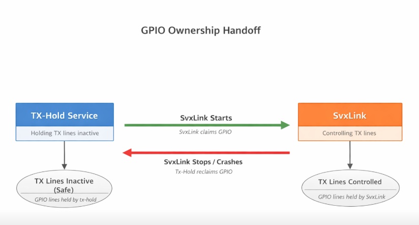
If the sense of the GPIOD pins is in the ACTIVE HIGH state for the PTT then in the tx-hold.sh script the following line needs to be change.
sudo nano /usr/local/bin/tx-hold.sh
#!/bin/bash
# Hold TX GPIO lines inactive indefinitely (safe for libgpiod2)

CHIP=gpiochip3
LINES="2 3 10 11"
#These are the TX_0, TX_1, TX_2 and TX_3
# Start gpioset in background
gpioset $CHIP $LINES=1 &
#change to $LINE=0 if the GPIOD sense is ACTIVE HIGH on the PTT
GPID=$!

# Keep the process alive so the GPIO ownership persists
while kill -0 $GPID 2>/dev/null; do
    sleep 60
done
Chapter 3 – setting the requirements of SvxLink
In the basic SvxLink.conf when initially installed, it has the capability of One RepeaterLogic, One SimplexLogic and and One ReflectorLogic. Running the version I have suggest will fail, as is build for a simple single channel operation, but it is easilly adaptable. Read on.
Now when we run the 2x and 4x boards, this means that we now need to double/quadruple up on the Logic forms. This is what will catch you out.
It is important to plan the operation. In the case of One Repeater setup working with one simplex node, there no changes will be necessary, but doubling up on these requirements will mean changes to the configuration. Referring to the image ther is a folder with a unconfigured master svxlink.conf, from where you can copy and paste sections to your new svxlink.conf, by opening two terminals to your device. In this way you can copy and paste [SimplexLogic] or [RepeaterLogic] into place and edit it to your configuration.
As an example I am going to use the 4x board scenario that has two repeaters and two Simplex radios attached (as in the presented svxlink.conf in chapter 2.) It was built in exactly the same way, paying careful attention to number of ports and lines.
So we shall need to go to the back office of the operation, the .tcl files that are located in /usr/share/svxlink/events.d/ .
Here there are many files but we shall need to copy ReflectorLogic.tcl and SimplexLogic.tcl into secondary copies of themselves, named according to the convention applied in the svxlink.conf. So according to that file the new copies of the files here will be Repeater2Logic.tcl and Simplex2Logic.tcl.
No other changes are required here. but we need to go back to the svxlink.conf to ensure that this changes are acceptable.
Our first concern is that these new Logic Sectors are recognise in [GLOBAL] as the first point. They must be declared or will not be included at run time.
The second concern is that when running to an svxreflector, that the [LinkToReflector] pointed to by LINKS = in the global sector contains all the intended links to be connected.
[LinkToReflector]
CONNECT_LOGICS=RepeaterLogic:9:,Repeater2Logic:9:,SimplexLogic:9:,Simplex2Logic:9:,ReflectorLogic
This indicates this to be the case. If you want to separate linking capabilities, such as one repeater and one simplex in one connection and the second repeater and simplex in another, then you can make a new [Link2ToReflector] , declare it at LINKS= so that the repeaters can run with individual identities, but link with the reflector independently. This will require a second [Reflector2Logic] with all the changes I have already described to incorporate it. This will permit the two identities to connect to the Reflector individually.
The ‘9’ in the lines above give a DTMF ‘9’ to be an acceptable command to the svxlink.conf. Sending 9# from any link with temporarily disconnect a repeater/simplex from the ReflectorLogic, and 91# restores the connection. Placing a string of characters in the line CONNECT_LOGICS=RepeaterLogic:9:N9AC, will indicate the stream connected or disconnected. when applying the DTMF sequence 9# or 91# for purpose of identification.
To stop svxlink from working simply type at the terminal:
sudo systemctl stop svxlink
To restart it (and verify it working) type:
sudo systemctl restart svxlink | tail -f /var/log/svxlink.log
The vertical bar ‘|’ instigates a concatenation of commands.
A reminder that gpio.conf and its service svxlink_gpio_setup.service are now deprecated, as is the daemon method of using rc.local on bootup. The systemd is by far the most efficient method of driving the svxlink runtime.
My final add-on is for fan control – still to be perfected – I have written a script, but needs debugging. I WILL UPDATE THIS SOON.