
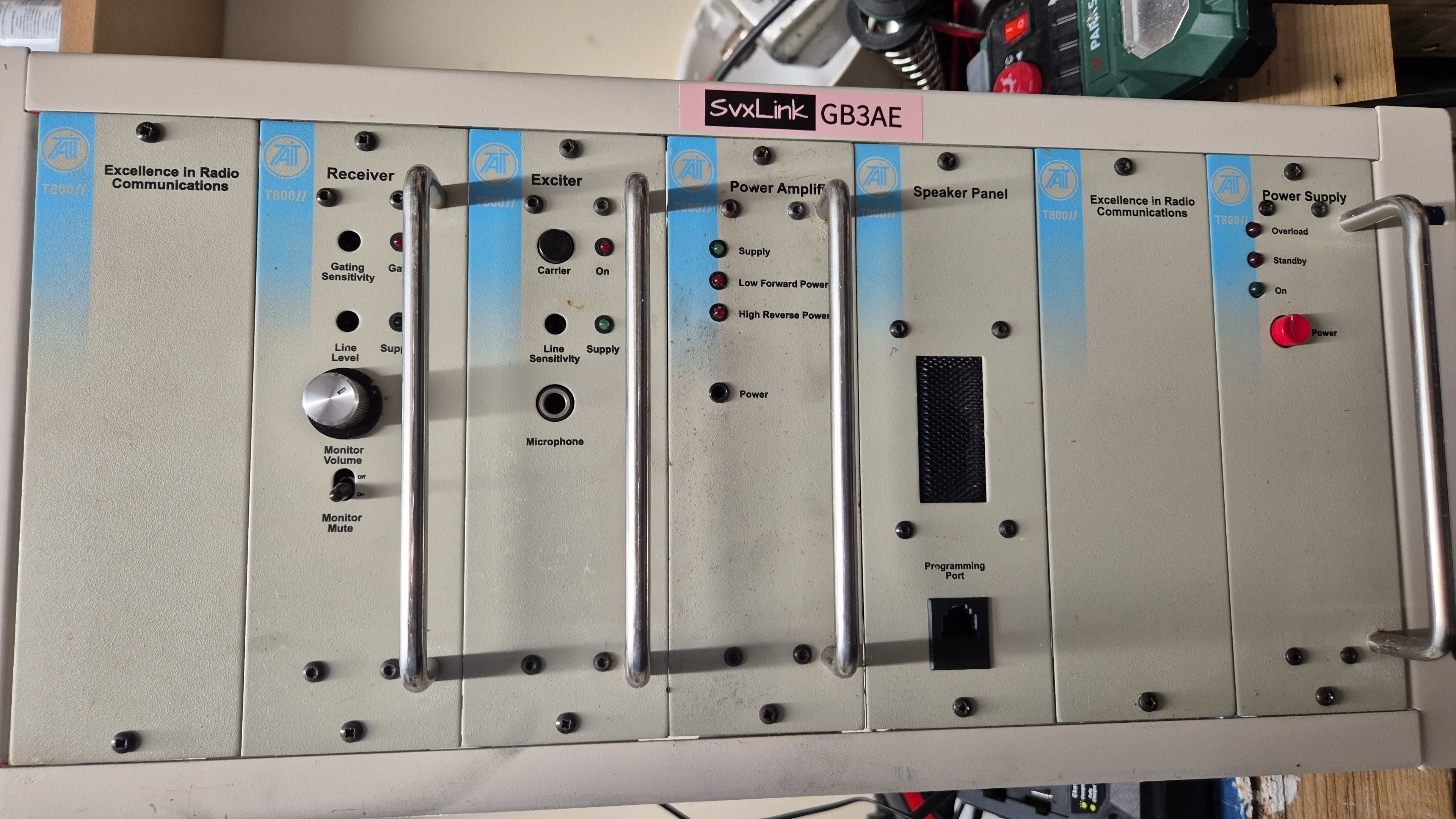
I am never one to ‘Look a Gift Horse in the mouth’, so when Simon G4USP said ” Do you want a VHF Repeater and some Beer Barrel filters, I did not say “no”.
I have been building repeaters for many years now initially from coupled transceivers like Motorola GM350, using Tait Main Frame repeaters was easy to achieve. I have already utilised several T800 Mk1 repeaters for UHF Repeaters and this T800 Mk2 was just a new challenge.
Challenge one – bring it into the Amateur Radio 145 MHz Band from it original Commercial Band operation – Tx 154 Mhz and Rx 162 Mhz.
Challenge two – to understand the complicated backplane for audio throughput.
Challenge three – conversion of the Beer Barrel Filters from Band Pass to Vari-Notch.
Challenge four – to place it under SvxLink Repeater Control Mode.
Challenge 1
The first challenger was to force-program the repeater into the Amateur Band, that actually turned out to be very easy. Although the warnings from the Tait software that the programming frequencies where not viable, the firmware was very happy and took the 145.6375 MHz for transmit and 145.0375 MHz, and the CTCSS programming, Flat Audio without complaint.
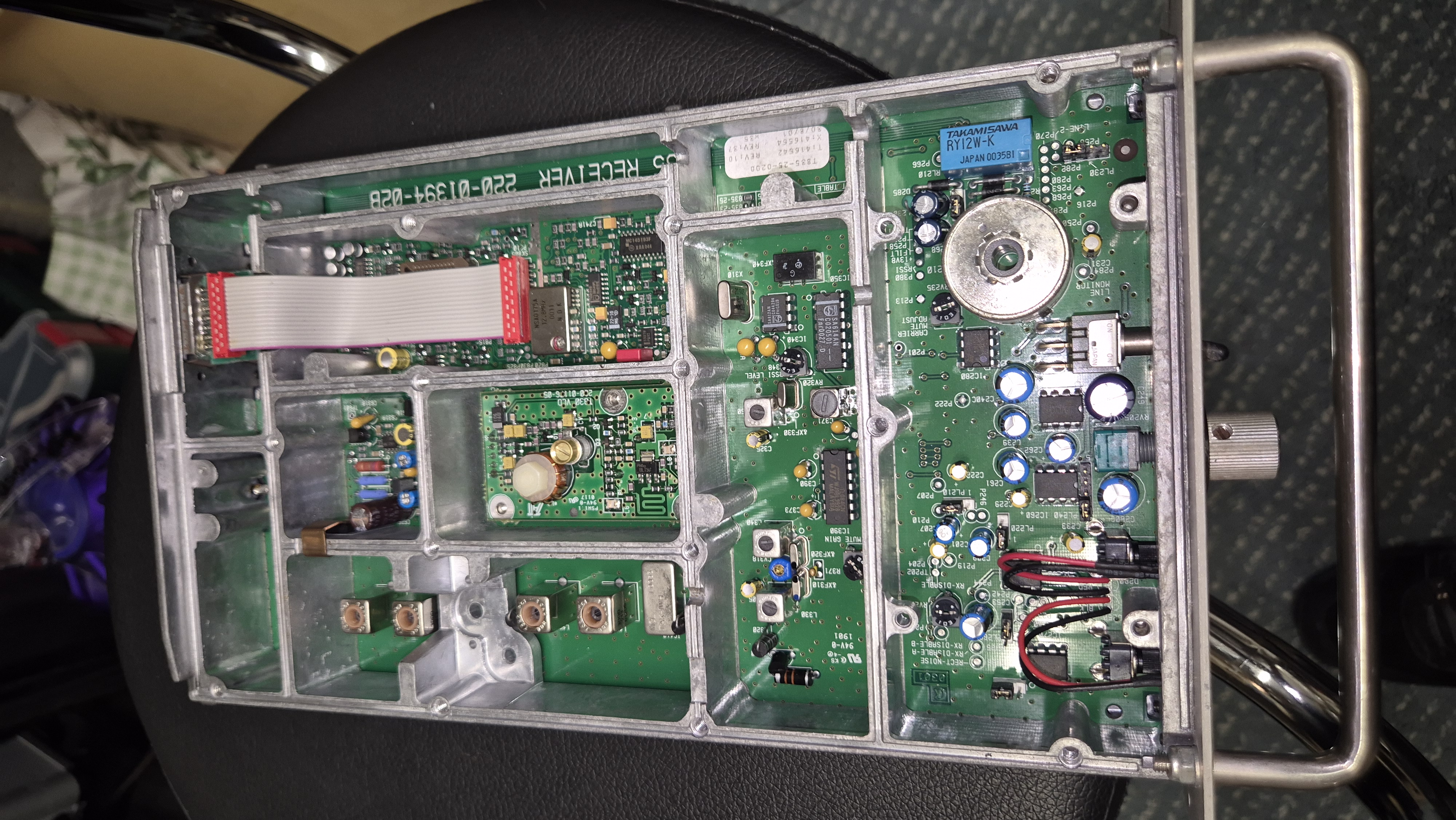
The next task was to modify the VXCO seen in the very centre of this image to the new frequencies.
As it happened it was extremely simple, with a bit of judicious de-soldering, I removed the coil (adjacent to the tubular capacitor) and with identical guage wire, wound and extra two turns on the Receiver VXCO and an extra single turn on the Transmitter VXCO, and resoldered them into place.
It was then a matter of powering the units and reading 9V on L1, by trimming the tubular capacitor.
For the Receiver, applying an decreasingly smaller input signal with a 1 kHz tone to the antenna socket at 145.0375 Mhz with CTCSS of 118.8, the chain of Toko coils were trimmed to obtained maximum Signal to Noise Ratio. That is until the cores of two of the two toko coils broke, and I had to order replacements.
Succesfully tuned, the receiver was good for service. The Exciter was similarly tuned, and produced the required 800 millwatt signal that gets ultimately fed to the Amplifier, that when test produced a steady 25 Watts, turned down from its potential 60 watt full output.
Challenge 2
The backplane was complicated enough, but I had already moved one link to enable the programming of the repeater, then moved it back to return it to full repeater use. But Tait had built these units into Repeater or Base Station use. As it happens and counterintuitively for our purposes Base Station is what we required, and it seems that this unit was already set for this fashion. The Repeater Setting, took the input audio and fed it directly to the output, which is not what we want at all as SvxLink was to perform this function, so Base Station is what we use.
As it turned out there were several models of backplane, and finding to correct one was imperative. Fortunately the webiste repeater-builder.com contains many documents for pre-loved equipments for the amateur radio enthusiast, and the correct version provided the answers. Connecting a DB-25 connector with the appropriate pins connected to the 2E0JJI USB-CM108 Interface set it ready for use.
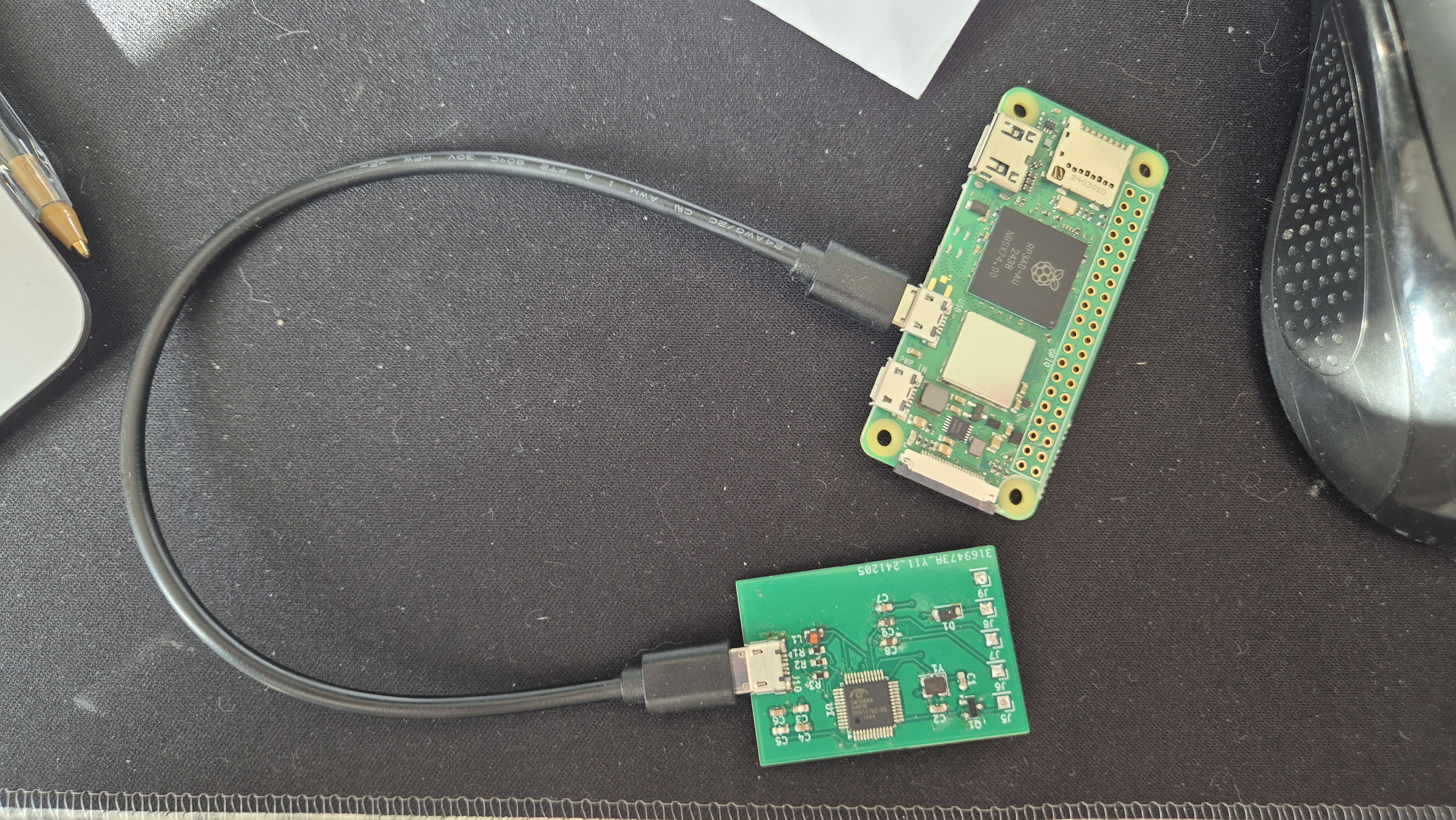
This is a 2E0JJI USB CM108 interface currently attached to a Raspberry Pi 02W. Practically all that is required for a repeater interface these days.
Because I use 64 bit Software, most of the Raspberry Pi range of small board computers can be used.
But not a Raspberry Pi-0W or Raspberry Pi 2B as they are incapable of 64 Bit operation. But I have kept a 32 Bit version of the software for these types and an Armbian version for the NanoPi-Neo computer.
Challenge 3
The original beer barrel filters were in fact used for the purpose as Radio RF Filters, and probably have never seen alcohol in their lives. They came to me as bandpass filters, but in that configuration, were no good at all. My experience with Cavity filters tuning were as Vari-Notch cavities, where they had the capacity (excuse the pun) of performing frequency pass and frequency reject in the same container, and were generally more efficient.
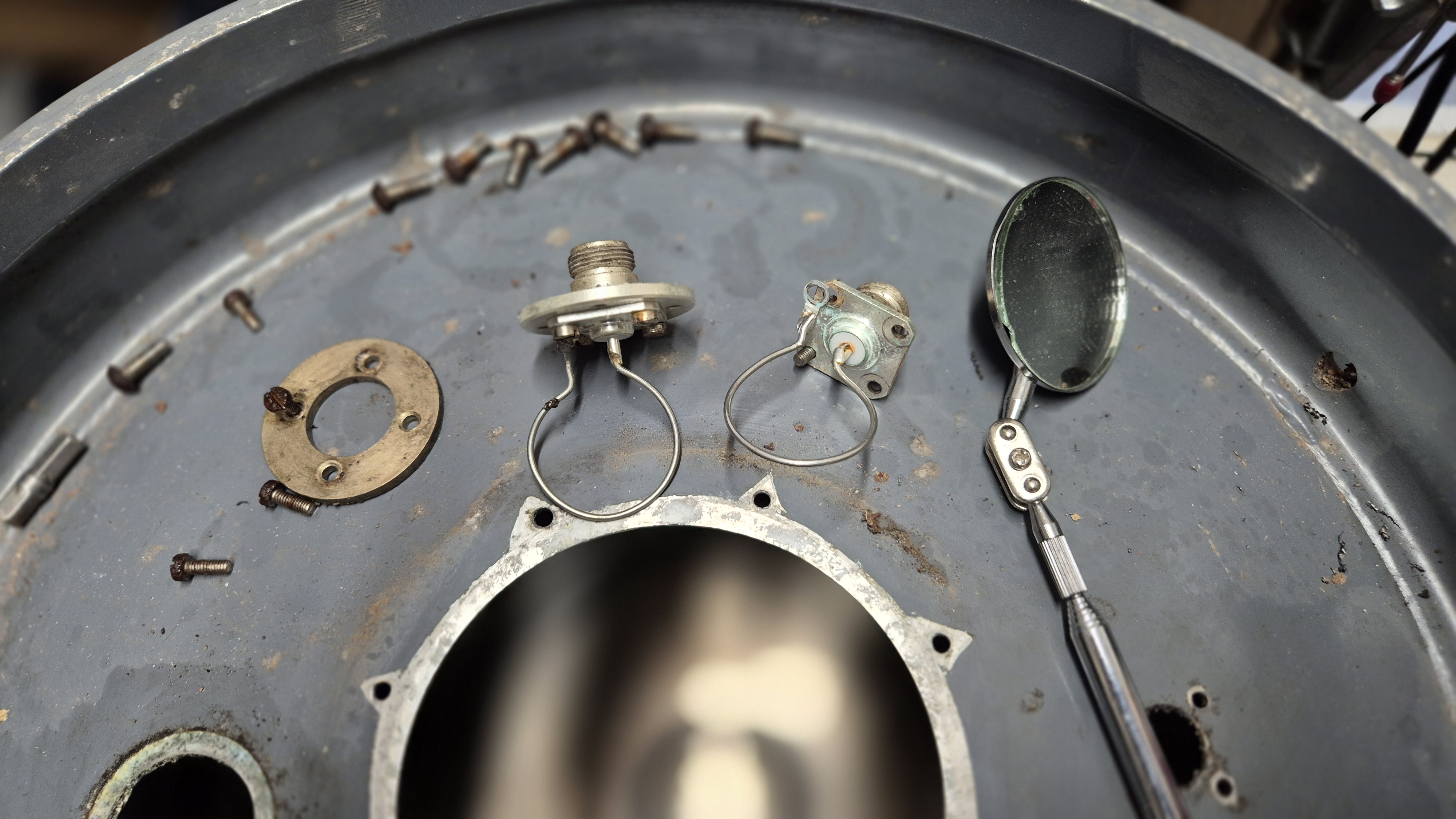
So I firstly removed the piston assembly from the centre, then removed the two single coils from the two holes at opposing sides of the top plate. Reaching inside with a mirror to remove the securing bolts, some of which were rusted. It was surprising how much moisture had accumulated in the base of the container (it wasn’t beer), that I had to mop out with kitchen paper.
The next task was to block the fixed-coil hole (the one with the 3mm holes) as this was now superfluous.
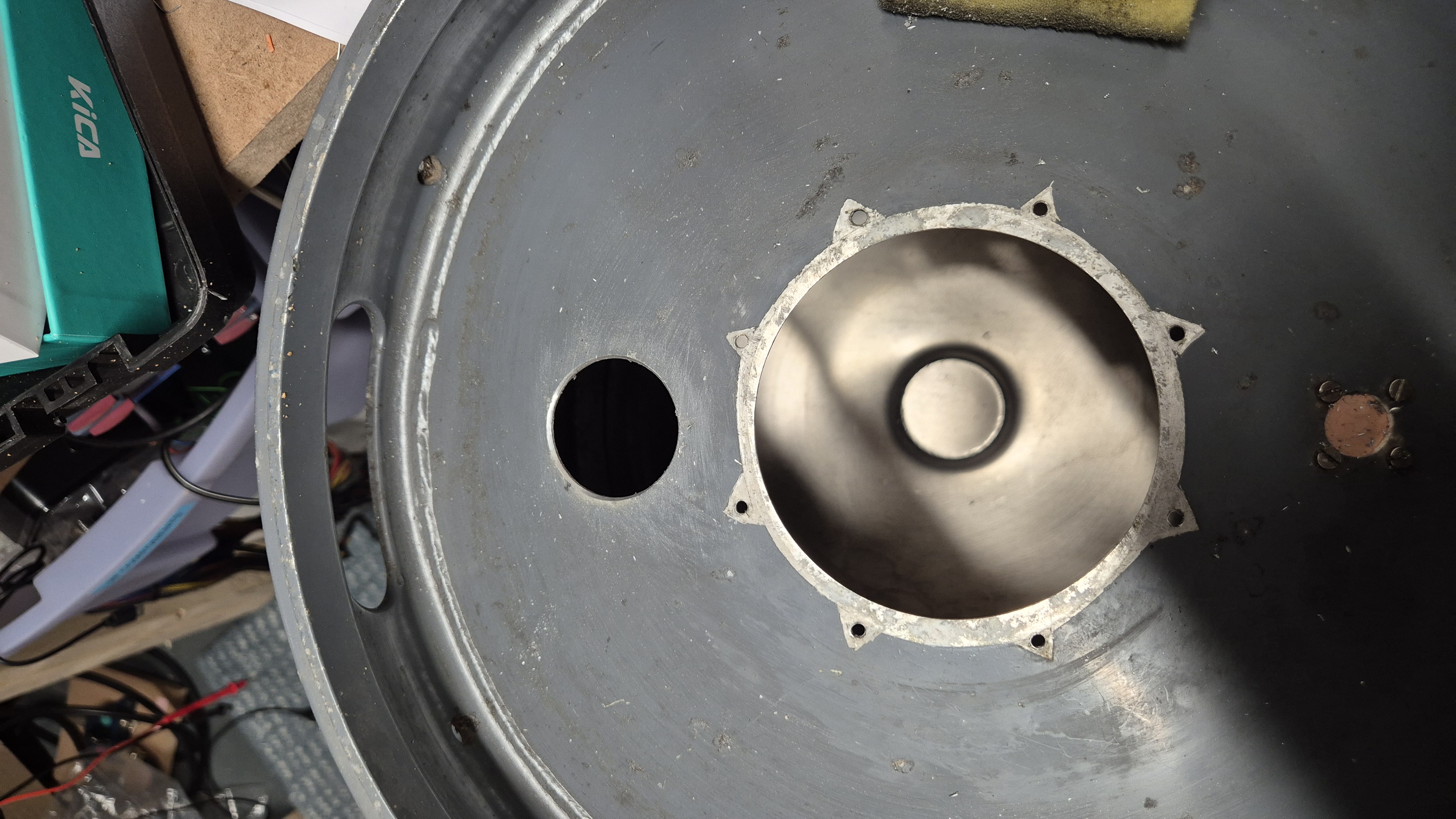
Next with the assistance of Kevin (AA3XV) my brother, we designed a cupolar to enable the insertion of a new plate, that carried two N-Type sockets, beside each other with a small hole adjacent for the purpose of tuning the pi-tank coil for the Vari-Notch tuner.
This consisted of a plastic ring as a surround, to be secured in a fixed position, with tap-and-die screws, to permit the inner plate to rotate and then be fastened with overlapping washers to prevent further rotation when tuned.
Because of the size of the N-type sockets, the remaining hole in the top plate had to be reamed out to 45mm, to allow the passage of the base nuts of the two sockets to pass cleanly, with the 50mm plate remain free to rotate in its cupola above the surface of the barrel.
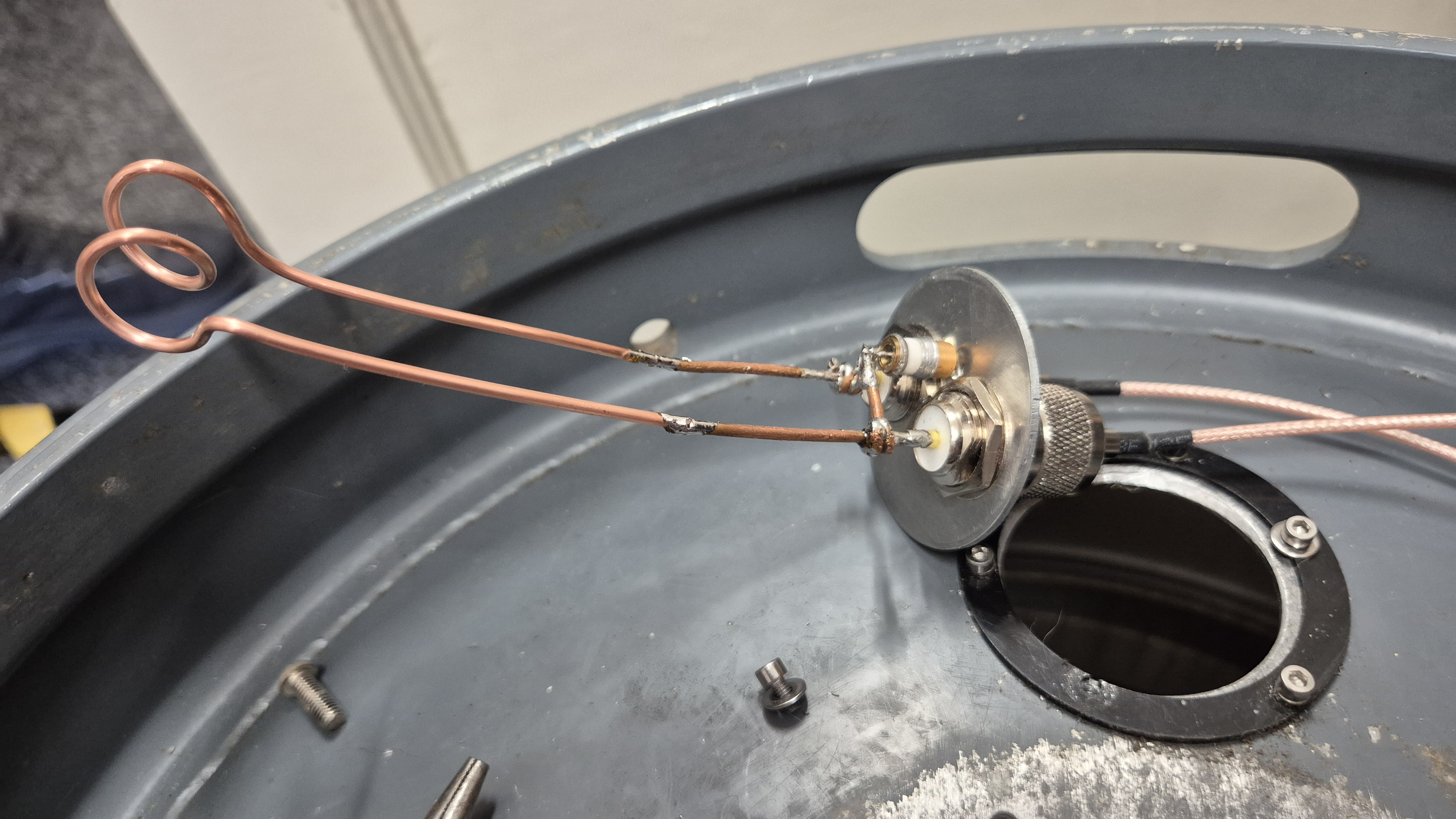
It took several attempts to find the optimum length of the legs of the insertion coil as can be seen with this final design. 12 guage wire with two turns in the coil, spaced to 20mm wide on a 12mm former. The tubular capacitor connects the bases of the legs together, clear of any other metal work. Tuning of the capacitor is achieved through the small hole in the plate to one side of the two sockets. The coil is then inserted in the cupolar, free to rotate initially until optimum position in the tuning is achieved, when the plate is secured to the outer ring.
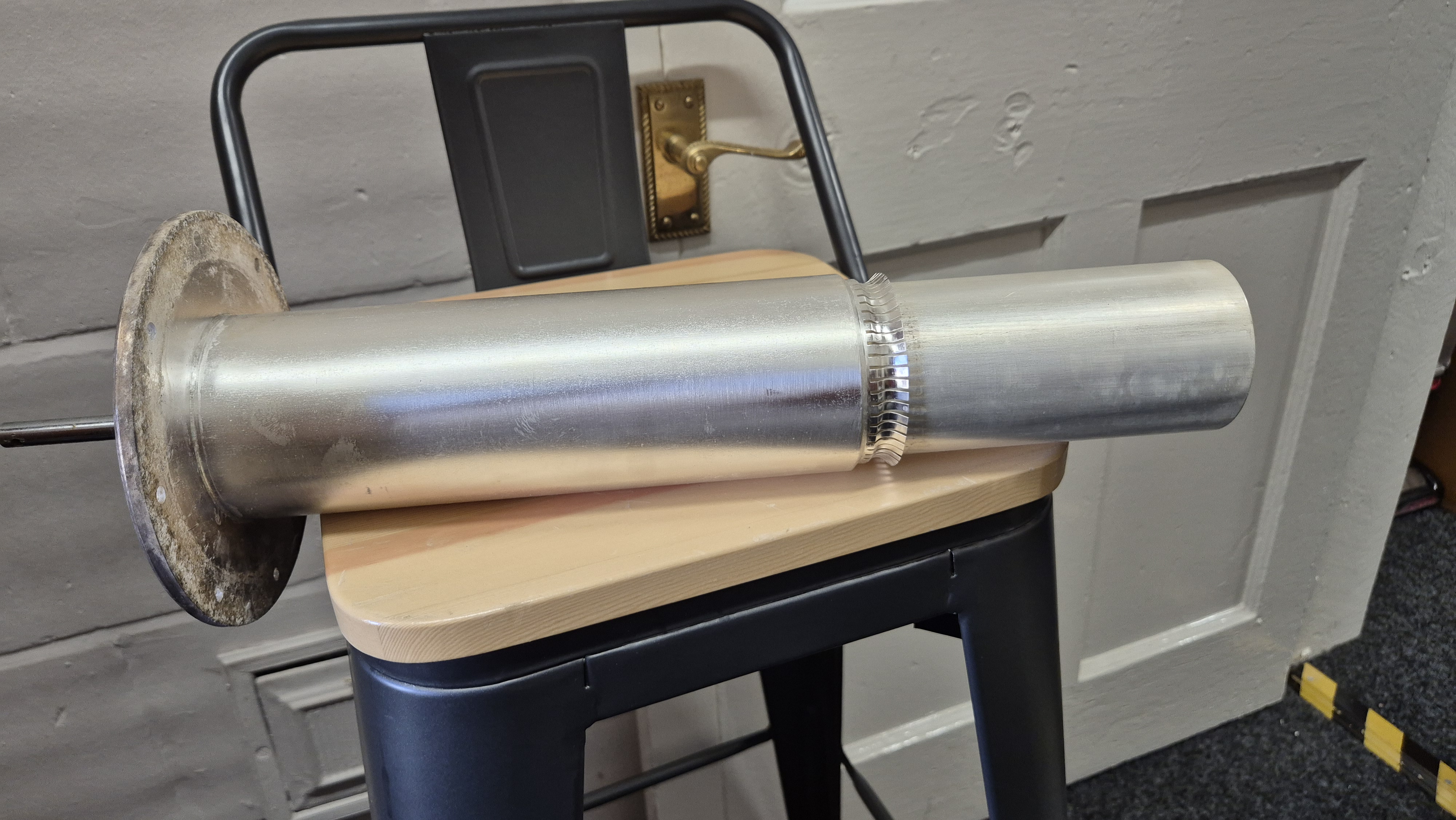
This is a piston assembly that tunes the frequency-pass of the barrel filter. The inner is withdrawn or pushed down with the rod to the left through its sleeving, that is then secured by a locking screw when the exact frequency pass is selected. The point at which the minimum insertion loss on the spot frequency that is achieved is extremely narrow down to micromillimetres.
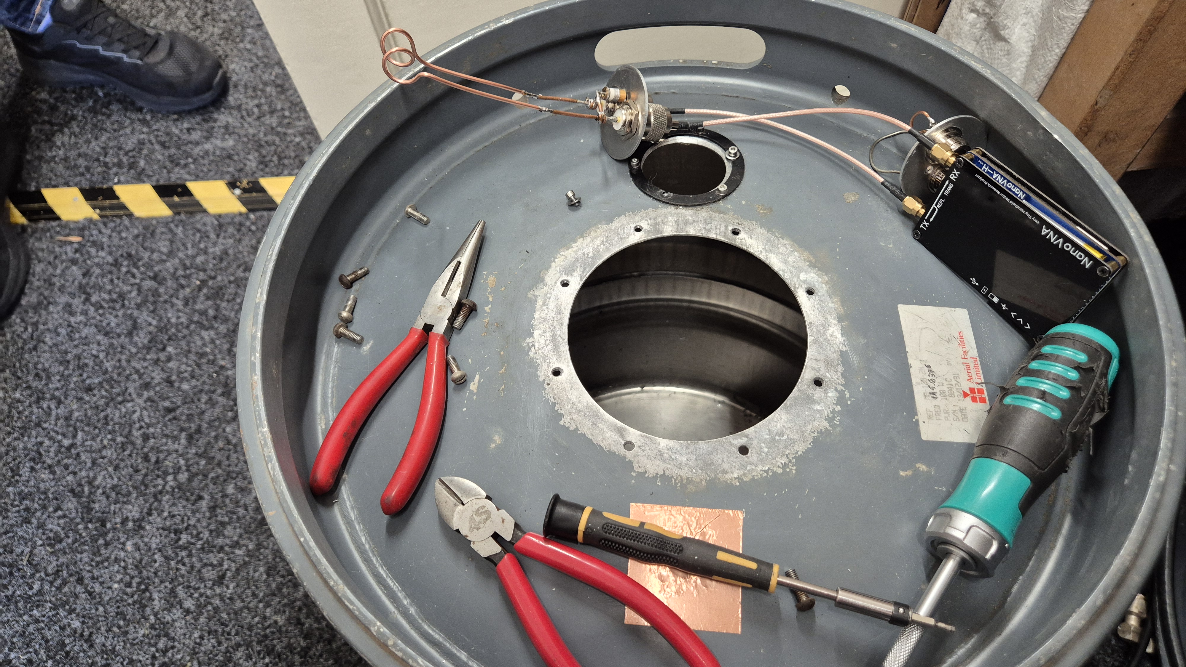
So prior to reinserting the piston assembly and the pi-tank coil, I wiped the interior of the barrel with kitchen paper to remove any remaining moisture and swarf from reaming out the tuning hole.
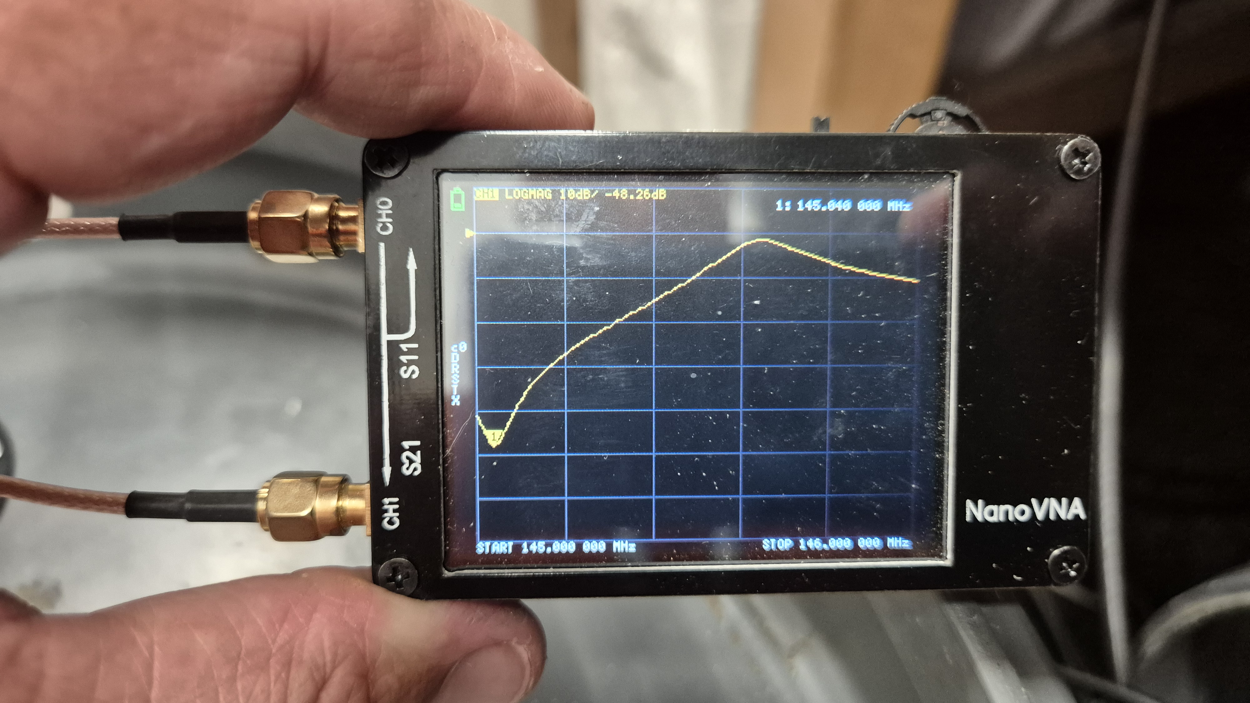
With the NanoVna set on S21 which is the only real portable tool for the job, we first adjust the piston to get the frequency pass aligned and lock it off with the screw.
The Start Frequency of the chart is 145 MHz and the Stop Frequency is 146 MHz. The desired pass frequency 145.6375 gives an insertion loss of between -.8 and -1.2 dB, not super good, but really – for a beer-barrel? Really adequate. At the other end of the range where the pointer is is the Reject Frequency, achieved by rotating the insertion coil and locking it off in the cupolar, then tuning the capacitor through the hole between the N-Type conectors.
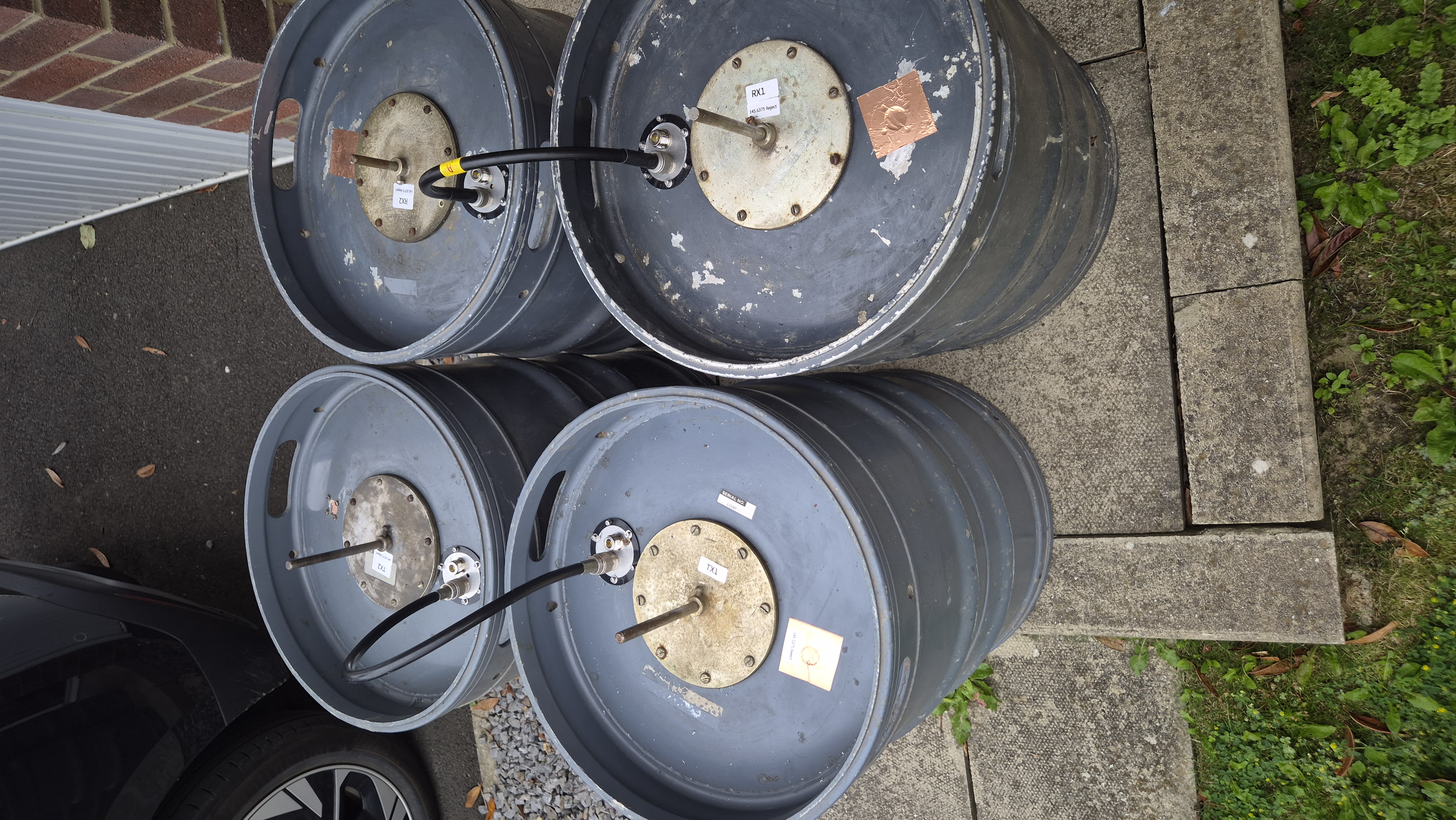
These are the four barrels ready to go to the site – with two of them tuned for the receive frequency rejecting the transmit frequency, and the other two as the description above for the Transmitter. The lengths of coax between each barrel was a 1/4 wave at the velocity factor of the coaxial cable in this case RG213. Yes – one of them was too long and was replace on site. I had a prepared crimped cable ready.
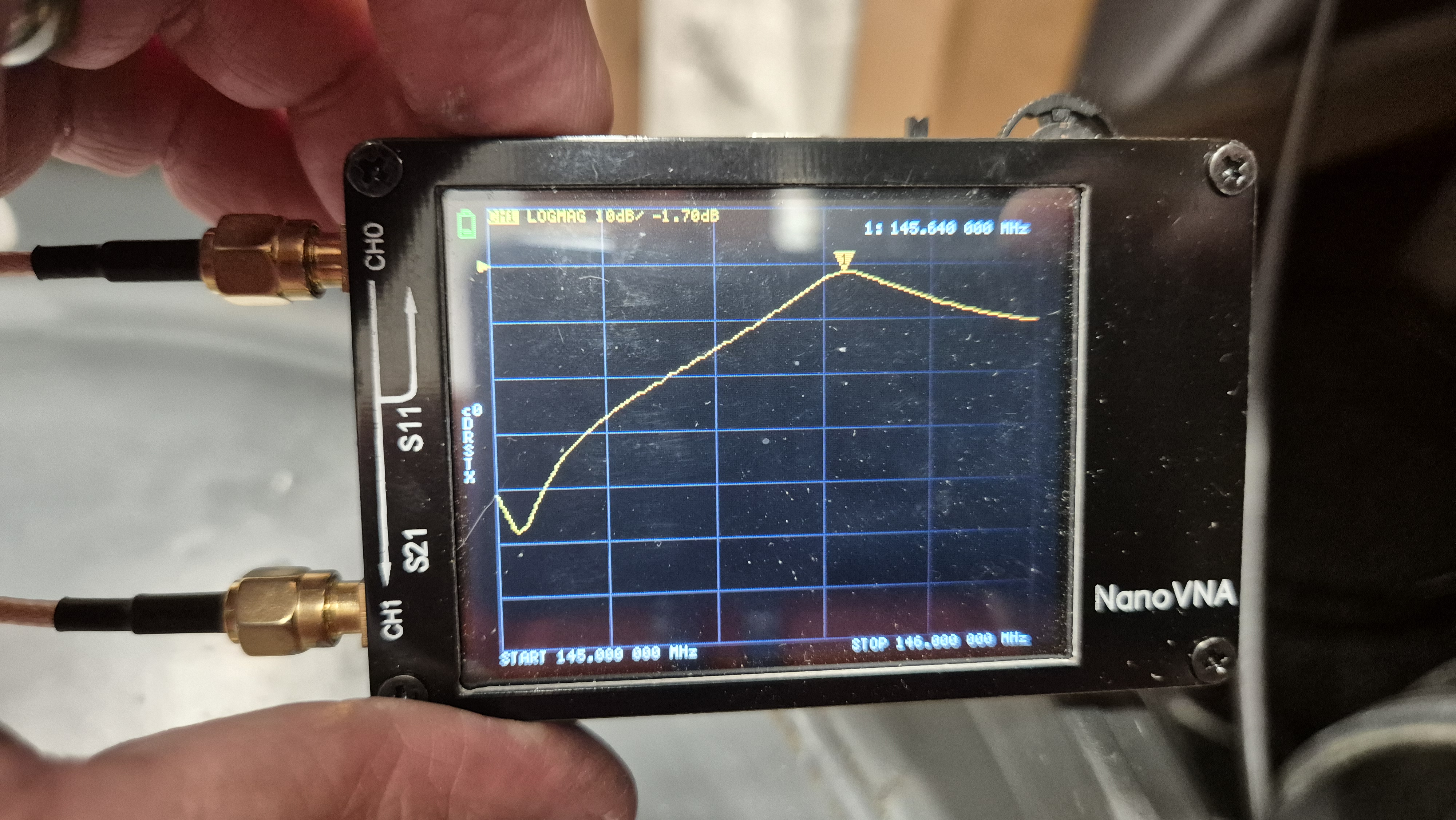
This was one of the barrels prior to installation, with a slightly higher insertion loss than desired at -1.70 dB
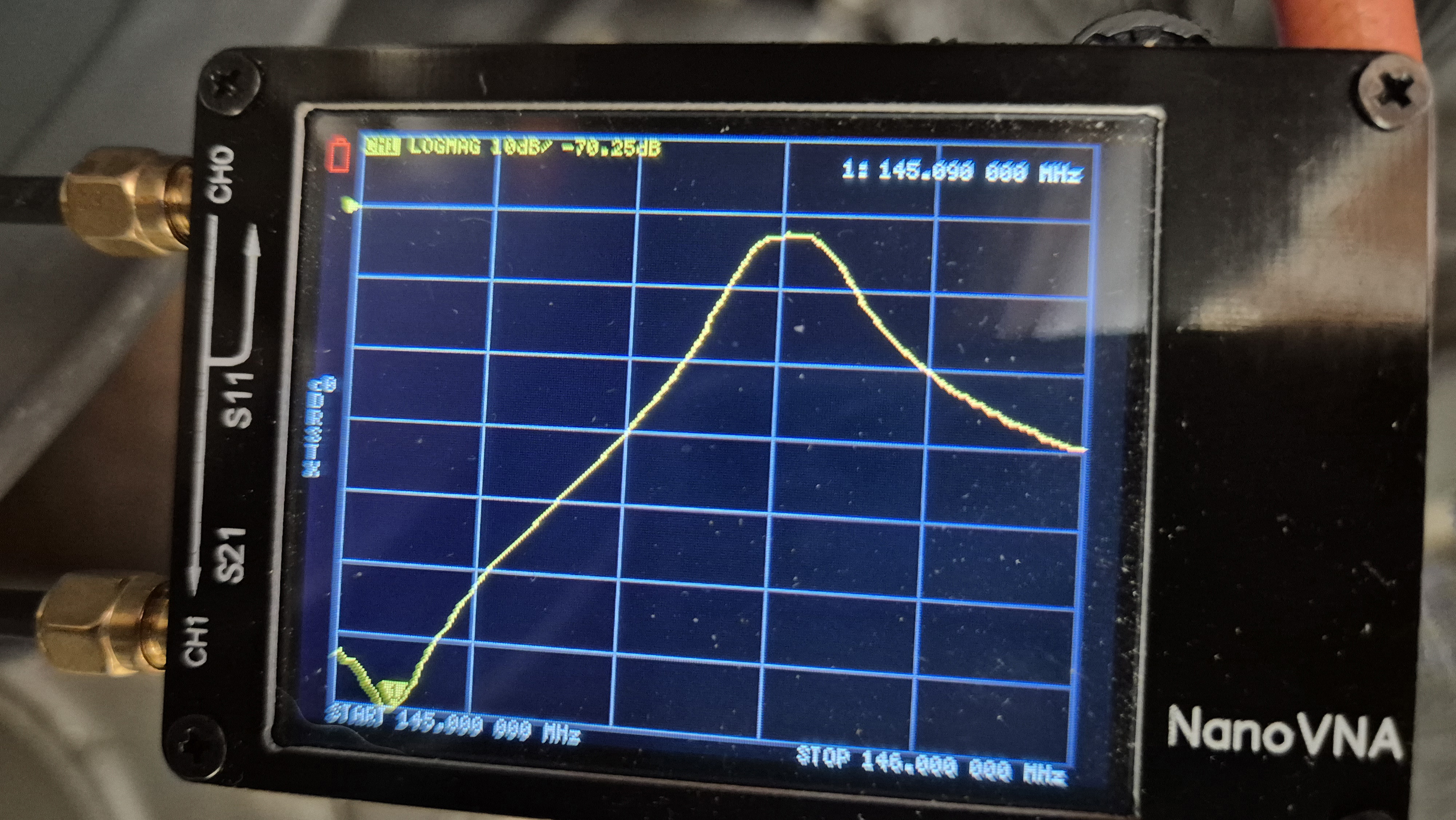
This was the result across two barrels in dasiy-chain in the transmit line that showed a rejection of -70.25 dB of the receive frequency 145.0375 MHz, and an insertion loss of around. -1.8 dB across both barrels. Despite tweaking them individually, I found that once in the daisy chain that they were able to be tuned together to be more tightly controlled, which was highly satisfying and really strategic to getting both legs working correctly. The result was an extremely clean operation.
The final stage – The SvxLink package.
Having worked for many years with Tobias Blomberg SM0SVX’s celebrated SvxLink software, there is nothing better that makes the repeater available and more importantly stable.
I have taken Tobias’ software and packaged it with a Python-controlled installation system and dashboard to provide a rapid deployment package, with accessibility for the purist to add whatever niceties he or she would like. I find that the standard package works suitably for most applications, including EchoLink, and connections to a working SvxReflector system, such as we have in the UK, NorthAmerica and Australia to which the repeater easily connects. However EchoLink in our case is not yet possible as we run our repeaters GB3AE and GB7NE on a 4G router that for technical reasons certain parts of the internet are not connectable without added expense to which the club is not prepared to extend.
However the access to the SvxReflector is still possible as a single UDP port provides that connection unhindered by the 4G blockage. For the moment that suits us. We know that solutions for EchoLink exist, but they are not being implemented right now.
Fortunately with foresight I did install rpi-connect to the repeater and I can administer the SvxLink at a distance.
SvxLink is better in some ways than AllStarLink as it is easier to manage. In the SvxReflector we use AllStarLink Nodes as Talkgroups to provide live activity, such as the NorthWest Allstar Group based around Morecambe Bay in Lancashire.
Final assembly
We are fortunate, that due to a donation of a 2m40 Full 19 inch rack cabinet, we have GB3AE ans GB7NE sharing accomodation in an environment that at least looks the part.
The antenna situation is not ideal but for our circumstances is better for performance than cost.
Here is the voice of the repeater – Callie introducing herself
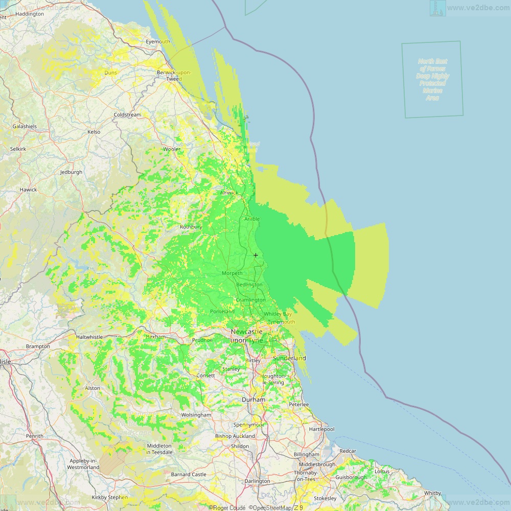
The final ERP for the repeater is 13 watts, but we have two antennas, an X200 for transmit and an X300 for receive, slightly lower than the transmit, but with slightly higher gain. The use of Tee for a single antenna was impractical as the result SWR was disastrous, and the power out loss significant. We cannot run to the cost of a circulator or hybrid connector so for the moment we are reasonably satisfied with the result. The coverage appears close to the a computer generated pattern and is attached below.